

The Challenge of Integrating Off-the-Shelf OLEDs
In the vast and rapidly expanding universe of do-it-yourself (DIY) electronics, few components offer the immediate visual feedback and aesthetic appeal of a small display. Among these, Organic Light-Emitting Diode (OLED) modules have surged in popularity, primarily due to their vibrant colors, high contrast, low power consumption, and compact form factors. A quick search on any online electronics marketplace reveals "a million and one cheap OLED display modules out there," readily available for a few dollars. These ubiquitous screens, often based on controllers like the SSD1306, are a staple for hobbyists, educators, and professional prototypers alike, enabling a myriad of projects from sensor readouts to miniature gaming consoles.
However, this abundance comes with a significant, often frustrating, caveat: their physical integration into a finished project. The vast majority of these modules are sold as bare printed circuit boards (PCBs), complete with exposed solder joints, sometimes fragile connectors, and highly variable dimensions. While perfectly functional in a breadboard or for initial testing, their unadorned nature presents a considerable hurdle when striving for a clean, professional, and robust final product. Mounting them neatly within an enclosure typically involves custom-designed 3D-printed bezels, makeshift brackets, or, in less fortunate cases, unsightly glue and exposed wires. These ad-hoc solutions not only compromise the aesthetic integrity of a build but can also introduce mechanical vulnerabilities, making the display susceptible to damage or misalignment. The lack of standardization in their physical footprints further exacerbates the problem, meaning a solution tailored for one module might not fit another, even if both are technically "SSD1306-compatible." This persistent frustration among makers has long highlighted a critical gap in the ecosystem of readily available electronic components: the absence of a standardized, easy-to-mount display solution.
Galopago’s Elegant Solution: A Standardized, Panel-Ready Module
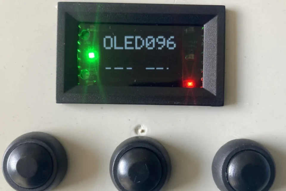
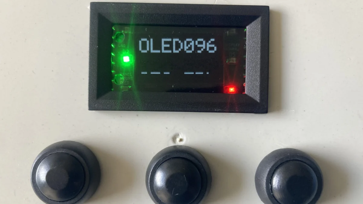
Responding directly to this widespread frustration, the innovative minds behind [Galopago] have engineered and unveiled a clever solution: a small, integrated OLED module specifically designed for clean panel mounting. This project, which has rapidly garnered attention within the DIY electronics community, addresses the core problem by packaging a standard SSD1306-compatible OLED screen into a robust, standardized enclosure, complete with a bezel for a flush, professional finish. The design ethos behind Galopago’s module is simple yet profound: to transform a functional but aesthetically challenging component into a plug-and-play solution that seamlessly integrates into custom test equipment, power supply builds, and other embedded systems.
The inspiration for this ingenious design was drawn from a familiar source: off-the-shelf panel displays commonly found in commercial power supplies, laboratory equipment, and industrial control panels. These professional-grade displays are inherently designed for clean integration, featuring standardized cut-out dimensions and integrated bezels that effortlessly conceal any rough edges or awkward gaps in the mounting aperture. By emulating this industrial design philosophy, Galopago has managed to bring a level of professional finish and ease of integration typically reserved for commercial products into the realm of hobbyist electronics. The result is a module that not only performs its primary function of displaying information but also elevates the overall quality and user experience of the host project.
Key Features and Accessibility
Galopago’s panel-mount OLED module is a testament to thoughtful engineering and user-centric design. At its heart, the build began with a readily available 48 x 29mm enclosure, a common dimension for power panel meters, ensuring that the final product benefits from established form factors. This choice immediately provides a sturdy, aesthetically pleasing housing that protects the delicate OLED and associated electronics.
Inside this compact enclosure, the module employs a two-PCB architecture, a design choice that enhances both functionality and ease of use. The primary PCB is dedicated to the core electronics necessary to run the display. This includes a voltage regulator, crucial for ensuring stable power delivery to the OLED and its controller, along with any other supporting components that manage the display’s operation. The use of a flat flex cable (FFC) connects the SSD1306-compatible OLED screen to this board, a common and reliable method of interfacing thin display panels.
The second PCB is ingeniously dedicated to user connectivity. It features a set of robust screw terminals, a critical inclusion that drastically simplifies wiring the display to external equipment. Unlike the often delicate and sometimes difficult-to-solder header pins or tiny solder pads found on bare OLED modules, screw terminals offer a secure, tool-free, and reconfigurable connection method, ideal for projects that may require field maintenance or easy component swapping. This dual-board approach separates the display’s sensitive control circuitry from its input/output interface, contributing to a more modular and user-friendly design.
Crucially, in the spirit of open-source collaboration that defines much of the DIY electronics community, Galopago has made all design files publicly available on GitHub. This open accessibility means that curious makers, aspiring engineers, and even small businesses can examine the schematics, PCB layouts, and potentially modify or adapt the design to suit their specific needs. This commitment to open hardware not only empowers others to replicate the module but also fosters a collaborative environment for further innovation and improvement. For anyone who frequently finds themselves needing to integrate a small display into custom test equipment, a portable gadget, or a fixed installation, this module presents a highly relevant and compelling solution.
A Journey from Frustration to Functional Design: The Chronology of Development
The creation of Galopago’s panel-mount OLED module is a classic tale of engineering innovation born from practical necessity. It charts a path from a common frustration experienced by countless electronics enthusiasts to the development of an elegant, open-source solution. Understanding this chronology provides insight into the iterative process of design and the thoughtful considerations that shaped the final product.
Identifying the Pain Point: The Genesis of an Idea
The genesis of the Galopago module can be traced back to a widely shared experience within the maker community: the struggle to neatly integrate bare OLED displays into finished projects. Imagine a scenario where a hobbyist has meticulously designed and built a custom power supply, a sophisticated sensor station, or a unique piece of test equipment. The functionality is robust, the code is optimized, but when it comes to adding a display for critical readouts, the aesthetic often falls short. Bare OLED modules, while cheap and powerful, are notoriously difficult to mount flush and cleanly. Their exposed PCBs, varied mounting holes (or lack thereof), and delicate ribbon cables often lead to projects looking unfinished or amateurish.
The original article aptly describes this as a situation where "they’re all assembled on bare PCBs and they’re all slightly different, and that frustrates efforts to mount them in a clean and tidy manner." This collective frustration, the endless cycle of trying to invent new mounting solutions for each new project, was the fertile ground from which Galopago’s idea sprouted. The realization was clear: there was a significant unmet need for a standardized, user-friendly display component that focused as much on integration as it did on functionality.
Inspiration from Industry Standards: Learning from Commercial Displays
With the problem clearly defined, the next logical step was to seek inspiration from existing solutions in related fields. The original article highlights a crucial insight: "The idea to pursue this came from off-the-shelf panel displays commonly used for power supply builds and other such equipment." This observation points to a deliberate decision to look beyond the immediate DIY ecosystem and draw lessons from established industrial practices.
Commercial panel meters, voltmeters, ammeters, and other embedded displays are engineered from the outset for seamless integration into equipment enclosures. They feature standard rectangular or circular cutouts, integrated bezels that hide mounting screws and raw edges, and robust connection terminals. This industrial approach prioritizes not just functionality but also durability, ease of installation, and a professional appearance. By reverse-engineering the principles behind these commercial units, Galopago aimed to distill their core advantages—standardized dimensions, integrated mounting, and clean aesthetics—and apply them to the popular, affordable OLED technology. This strategic choice bypassed the need to reinvent mounting solutions from scratch, instead leveraging decades of industrial design wisdom.
Design Phase: Iteration and Component Selection
The transition from concept to concrete design involved several critical decisions regarding component selection and architectural layout.
-
Enclosure Adaptation: The choice of a "48 x 29mm enclosure grabbed from an off-the-shelf power panel meter" was a cornerstone of the design. This immediately provided a robust, pre-manufactured housing with a bezel, eliminating the need for custom fabrication of the most challenging part of the module. This standardized size also ensures compatibility with existing panel cutouts, simplifying integration for users. The enclosure not only offers physical protection but also dictates the overall form factor and the area available for internal components.
-
Dual PCB Approach: A key innovation was the decision to split the module’s electronics across two PCBs.
- Display Logic Board: One PCB was designated to "hold the regulator and other equipment to run the display." This board houses the SSD1306 controller (or an equivalent chip integrated into the OLED module itself), power conditioning circuitry (like the voltage regulator to convert input voltage to the display’s required voltage, typically 3.3V or 5V), and potentially level shifters if the display operates at a different logic voltage than the host microcontroller. This board is directly connected to the OLED via a flat flex cable (FFC), a standard, compact, and reliable method for interfacing thin display panels.
- I/O Terminal Board: The second PCB was dedicated to "carrying a set of screw terminals that make it easy to wire up the display to a piece of equipment." This separation is highly advantageous. It isolates the potentially delicate display logic from the more robust and frequently handled power and data connections. Screw terminals provide a far more secure and user-friendly connection than soldering directly to the main display board, minimizing the risk of damage during wiring and allowing for easy disconnection and reconnection.
-
SSD1306 Compatibility: The explicit mention of "SSD1306-compatible OLED screen" signifies a deliberate choice to leverage the most common and well-supported small OLED controller on the market. This ensures broad compatibility with existing libraries and code examples for popular microcontrollers like Arduino, ESP32, and Raspberry Pi, making the module instantly accessible to a vast community of developers.
Prototyping and Refinement: Bringing the Vision to Life
With the design principles and component choices established, the next phase would have involved rigorous prototyping and refinement. This iterative process typically includes:
- PCB Layout and Fabrication: Designing the two PCBs to fit precisely within the chosen enclosure, ensuring proper clearances, thermal management for the regulator, and robust traces for power and data. The design files (Gerber files) would then be sent to a PCB manufacturer.
- Component Sourcing and Assembly: Acquiring all necessary components—OLED screen, voltage regulator, capacitors, resistors, screw terminals, and the enclosure itself—and assembling the first prototypes. This often involves a mix of surface-mount technology (SMT) for compact components and through-hole for connectors.
- Initial Testing: Powering up the module, verifying voltage levels, and running basic display tests to ensure the OLED functions correctly and communicates with a test microcontroller (e.g., displaying "Hello World").
- Fit and Finish Evaluation: Physically installing the module into a dummy panel cutout to assess the fit of the bezel, the alignment of the screw terminals, and the overall aesthetic. Adjustments might be made to the PCB dimensions or mounting points based on these observations.
- Robustness Testing: Evaluating the mechanical stability of the assembled module, ensuring the FFC connection is secure, and that the screw terminals can withstand repeated wiring.
- Documentation: As the design stabilizes, creating clear documentation, including schematics, bill of materials (BOM), and assembly instructions, to support the open-source release.
This systematic approach, moving from problem identification to inspired design and through meticulous prototyping, ultimately yielded the polished, user-friendly panel-mount OLED module that Galopago has shared with the world.
Under the Hood: Supporting Data and Technical Insights
The elegance of Galopago’s panel-mount OLED module lies not just in its user-friendliness but also in the thoughtful technical choices that underpin its design. A deeper dive into these elements reveals why this solution is so effective and how it leverages existing technologies to achieve its goals.
The SSD1306 Ecosystem: A Deep Dive into OLED Technology
At the core of the Galopago module is an SSD1306-compatible OLED screen. The SSD1306 is a single-chip CMOS OLED/PLED driver with a controller for organic light emitting diode dot-matrix graphic display systems. Its prevalence in the hobbyist market is due to several key factors:
- Cost-Effectiveness: SSD1306-based OLEDs are incredibly affordable, making them accessible for a wide range of projects.
- Compactness: The controller is often integrated directly onto the display’s flex cable or a small breakout board, leading to very small module sizes.
- Communication Protocols: The SSD1306 supports both I²C (Inter-Integrated Circuit) and SPI (Serial Peripheral Interface) communication protocols.
- I²C: This two-wire interface (SDA and SCL) is highly popular for its simplicity and ability to connect multiple devices to a single bus. It’s often the default for smaller OLEDs. While slightly slower than SPI, it requires fewer pins on the microcontroller, making it ideal for projects with limited I/O.
- SPI: A faster, four-wire interface (MOSI, MISO, SCK, CS), SPI is preferred for applications requiring higher data throughput, such as fast animations or complex graphics. Galopago’s design likely accounts for either or both, given the general compatibility.
- Common Resolutions: These displays typically come in resolutions like 128×64 or 128×32 pixels, perfect for displaying short text messages, small icons, sensor readings, or simple graphs.
- Power Efficiency: OLED technology itself is known for its low power consumption, especially when displaying darker content, as pixels are individually lit. The voltage regulator on Galopago’s main PCB ensures the display receives a stable and correct voltage (often 3.3V or 5V, depending on the specific module and regulator chosen), protecting it from fluctuations from the host system.
Understanding the SSD1306 is crucial because its widespread adoption means a rich ecosystem of software libraries, examples, and community support is available. This significantly lowers the barrier to entry for developers using Galopago’s module, as they can leverage existing codebases rather than writing display drivers from scratch.
Modular Design Philosophy: The Advantages of Separate PCBs
Galopago’s decision to use two distinct PCBs—one for the display logic and one for the screw terminals—is a testament to sound modular design principles.
- Isolation of Functionality: Separating the sensitive display driving circuitry from the robust, user-facing I/O terminals prevents potential interference. It also means that if a terminal is damaged or a wire is pulled too hard, the core display logic is less likely to be affected.
- Ease of Assembly and Repair: Manufacturing and assembling two smaller, simpler boards can sometimes be more efficient than one complex board. Furthermore, if a component on the I/O board (like a screw terminal) fails, it might be possible to replace just that board, rather than the entire display module.
- Flexibility and Customization: This modularity could, in theory, allow for future variations. For instance, an alternative I/O board could be designed with different connectors (e.g., JST, header pins, or even a USB-C for power and data) without altering the display logic board. This enhances the adaptability of the core design.
- Reduced Stress on Components: Screw terminals, while convenient, involve mechanical stress when wires are inserted and tightened. Placing these on a separate, dedicated board reduces the mechanical strain on the display’s main PCB, which typically houses more delicate components.
Standardized Enclosures and Mounting Solutions
The choice of a "48 x 29mm enclosure grabbed from an off-the-shelf power panel meter" is perhaps the most significant design decision from an integration perspective.
- Universal Compatibility: By adopting a common industrial form factor, Galopago’s module slots neatly into existing panel cutouts, eliminating the need for custom enclosure design or intricate modification. This saves immense time and effort for makers.
- Integrated Bezel: The enclosure’s inherent bezel covers any imperfections in the panel cutout, providing a clean, flush, and professional appearance. This is a stark contrast to bare OLEDs, which often leave ugly gaps or require elaborate 3D-printed bezels that may not perfectly match the enclosure material or color.
- Robust Protection: Standard panel meter enclosures are designed to be durable, protecting the delicate display and electronics from dust, splashes, and minor impacts, which bare PCBs cannot offer.
- Simplified Bill of Materials (BOM): Sourcing a standard enclosure is far easier and often cheaper than designing and manufacturing a custom one, especially for low-volume projects.
Open-Source Hardware: Empowering the Maker Community
The availability of design files on GitHub is more than just a gesture; it’s a fundamental aspect of the project’s value proposition.
- Transparency and Trust: Open-sourcing the design builds trust within the community, allowing users to inspect the schematics and layouts, understand how it works, and verify its quality.
- Community Contribution: Other developers can contribute improvements, identify potential issues, or even fork the project to create specialized versions (e.g., different OLED sizes, different power inputs).
- Educational Value: The design serves as an excellent educational resource for aspiring electronics engineers, demonstrating practical PCB layout, component selection, and modular design principles.
- Reduced Barriers to Entry: For those who wish to build the module themselves or integrate it into a larger custom PCB, the open files provide all the necessary information, accelerating their development process.
- Long-Term Viability: An open-source project often has a longer lifespan and broader impact than a closed-source one, as its maintenance and evolution can be distributed across a community.
Cost-Benefit Analysis for DIY Enthusiasts
From a practical standpoint, Galopago’s module offers a compelling cost-benefit proposition:
- Reduced Design Time: The most significant saving is in design and prototyping time. No need to design custom mounting brackets, 3D print bezels, or figure out power regulation from scratch.
- Professional Finish: The module provides a professional look that is difficult and costly to achieve with bare OLEDs, enhancing the perceived value of any project.
- Enhanced Durability: The enclosure protects the display, potentially increasing the lifespan of the project.
- Ease of Assembly: Screw terminals make wiring straightforward, reducing assembly time and the likelihood of wiring errors.
- Marginal Cost Increase: While the assembled Galopago module will likely cost more than a bare OLED, the added expense is offset by the savings in time, materials (for custom mounting), and the significant improvement in quality and usability. For many, the convenience and professional finish will far outweigh the slight increase in component cost.
In essence, Galopago has taken a fragmented and often frustrating component and transformed it into a cohesive, user-friendly, and professionally integrated solution, leveraging smart design and open-source principles.
Community Engagement and Expert Perspectives: Official Responses and Reception
While the term "official responses" typically refers to corporate statements or governmental reactions, in the context of a community-driven open-source hardware project, it translates to the developer’s stated intentions, the project’s reception within the maker community, and the insights of experts in DIY electronics. Galopago’s module, though nascent, is poised to address a significant niche, and its impact can be anticipated through these lenses.
Galopago’s Vision: Addressing a Niche but Critical Need
Galopago’s initiative itself serves as an "official response" to a long-standing community problem. The very act of designing and releasing this module demonstrates a clear understanding of a specific pain point that many makers and engineers encounter regularly. Their implicit statement is: "We recognize the difficulty of integrating bare OLEDs cleanly, and here is a practical, open-source solution inspired by industrial best practices."
This vision is critical because it moves beyond merely providing a component; it offers a complete, integrated solution. In a world where components are increasingly commoditized, the value often shifts from the raw part itself to how easily and effectively it can be integrated into a larger system. Galopago’s focus on "usability" and "tidiness" indicates a mature understanding of what makes a DIY project truly satisfying and professional-looking. By making the files open-source, Galopago also officially endorses the principles of collaboration and community-driven development, inviting others to inspect, build upon, and improve the design.
Early Community Feedback and Anticipated Adoption
Upon its release, a project like Galopago’s typically generates immediate interest within online forums, social media groups, and platforms dedicated to electronics hobbyists (such as Hackaday.com, Reddit’s r/electronics, EEVblog forums, etc.). Initial feedback is likely to be overwhelmingly positive, especially from those who have personally struggled with OLED mounting.
- Relatability: The problem statement—"frustrates efforts to mount them in a clean and tidy manner"—resonates deeply with the target audience. Many will immediately recognize their own past struggles.
- Practicality: The solution is inherently practical. It doesn’t require specialized tools or advanced manufacturing techniques from the end-user beyond a standard panel cutout.
- Open-Source Appeal: The availability of files on GitHub is a significant draw, enabling individuals to replicate the module, learn from its design, or even adapt it for specific needs. This transparency builds trust and encourages wider adoption.
- "Why didn’t I think of that?" Factor: Simple, elegant solutions to common problems often elicit this reaction, indicating a well-executed design that seems obvious in retrospect.
Anticipated adoption could be strong, particularly among:
- Test Equipment Builders: Individuals creating custom power supplies, multimeters, function generators, or data loggers will find the clean integration highly appealing.
- Prototypers: Engineers developing product prototypes can quickly integrate a display that looks polished, saving time on enclosure design.
- Educators: The module could be an excellent teaching tool, demonstrating good design practices and modularity.
- Case Modders/Enthusiasts: Anyone looking to add a display to a PC case, a retro gaming console, or an appliance will appreciate the professional finish.
The success of similar "usability hacks" featured on platforms like Hackaday suggests that solutions to common, practical problems often gain significant traction and become widely adopted within the community.
The Role of "Usability Hacks" in the DIY Ecosystem
The Hackaday article itself highlights other "fun OLED hacks," including "this interesting effort to whip up displays from scratch in a home lab." This comparison is telling. While making OLED displays from scratch is an incredible feat of fundamental science and engineering, Galopago’s project operates at the other end of the spectrum: a "usability hack."
Usability hacks are crucial for the overall health and progress of the DIY ecosystem for several reasons:
- Lowering Barriers to Entry: By simplifying common integration challenges, usability hacks make more complex projects accessible to a broader audience. If a maker spends less time struggling with basic mounting, they have more time and energy to focus on the core functionality and innovation of their project.
- Elevating Project Quality: These hacks directly contribute to a higher standard of finished DIY projects. A project that looks professional is often taken more seriously, whether it’s for a competition, a portfolio, or even a potential product.
- Fostering Innovation: When routine problems are solved with standardized solutions, creativity is unleashed. Makers are freed from repetitive tasks and can channel their efforts into novel functionalities, advanced algorithms, or unique user interfaces, rather than wrestling with physical integration.
- Building Community Knowledge: Open-source usability hacks serve as blueprints, demonstrating effective design patterns that others can learn from and apply to different contexts. They become part of the collective knowledge base of the community.
In essence, Galopago’s panel-mount OLED module, by providing a clean, standardized, and open-source solution to a pervasive problem, acts as a force multiplier for innovation and quality within the DIY electronics world. Its "official response" is a practical demonstration of how thoughtful design can empower an entire community.
Broader Implications for DIY Electronics and Beyond
Galopago’s panel-mount OLED module, while a seemingly modest innovation, carries significant broader implications for the DIY electronics community, embedded system design, and the trajectory of modular hardware development. Its impact extends beyond simply making displays easier to mount; it touches upon how makers approach projects, the quality of their output, and the future of component integration.
Elevating the Standard of Hobbyist Projects
One of the most immediate and profound implications of Galopago’s module is its potential to significantly elevate the aesthetic and functional standards of hobbyist projects. Historically, a common distinguishing factor between professional prototypes and DIY creations has been the "fit and finish." Bare PCBs, exposed wires, and makeshift mounting solutions often betray the amateur nature of a build, even if the underlying electronics and code are brilliant.
By providing an off-the-shelf solution for clean display integration, Galopago empowers makers to produce projects that look much more polished and commercially viable. This isn’t just about vanity; a professional appearance often implies better durability, thoughtful design, and attention to detail. For students presenting projects, hobbyists showcasing their work online, or even small-scale entrepreneurs prototyping a new product, the ability to seamlessly integrate a display can dramatically enhance perceived quality and credibility. This subtle shift could encourage a broader focus on industrial design within the DIY community, moving beyond pure functionality to encompass usability and aesthetics as integral parts of the design process.
Paving the Way for Future Modular Components
Galopago’s module exemplifies a growing trend towards modularity and standardization in DIY electronics. Just as the Arduino platform standardized microcontroller interfaces and the Raspberry Pi established a single-board computer ecosystem, solutions like this module demonstrate the value of encapsulating complex functionality (display driving, power regulation, user interface) into a simple, standardized, and easily integrable package.
This approach suggests a future where more "building blocks" are available as self-contained, panel-mountable, or otherwise cleanly integratable units. Imagine standardized modules for:
- Input Devices: Panel-mount rotary encoders with integrated debouncing, button arrays with pull-ups, or joystick modules.
- Connectivity: Standardized Wi-Fi/Bluetooth modules with integrated antennas and robust connectors.
- Sensor Hubs: Multi-sensor modules with a single standardized output interface and clean mounting options.
This modular philosophy accelerates development by allowing makers to focus on the unique aspects of their projects rather than repeatedly solving common integration challenges. It could foster an ecosystem of interoperable hardware components, similar to how software libraries abstract away low-level complexities.
Fostering Innovation Through Accessibility
By lowering the barrier to entry for clean display integration, Galopago’s module indirectly fosters innovation. When makers spend less time on tedious tasks like designing custom bezels or troubleshooting unstable power to a bare display, they gain valuable time and mental bandwidth to:
- Experiment with new features: Incorporate more complex functionalities into their projects.
- Refine user interfaces: Focus on creating intuitive and engaging display layouts and interactions.
- Tackle more ambitious projects: Embark on designs that previously seemed too daunting due to integration challenges.
- Learn advanced concepts: Dedicate more time to understanding core electronics, programming, or data analysis relevant to their project, rather than basic hardware assembly.
This accessibility democratizes advanced project development, enabling a wider range of individuals, regardless of their proficiency in mechanical design or enclosure fabrication, to bring sophisticated ideas to life.
The Future Landscape of Embedded Displays
Galopago’s project might also influence the future design of other small embedded displays. Manufacturers of bare OLEDs and similar components might take note of the demand for integrated, panel-mount solutions. While the market for bare modules will always exist for highly customized applications, there could be a growing segment for "pro-ready" versions that incorporate some of Galopago’s design principles directly from the factory. This could lead to:
- Standardized dimensions and mounting holes: Even for bare modules, a consensus on common footprints could emerge.
- Integrated bezels or mounting flanges: More modules might come with built-in features for clean panel integration.
- Robust connection options: Standardized, larger pitch connectors or even pre-wired cables could become more common.
Such developments would further streamline the prototyping and product development process for both hobbyists and small businesses.
Call to Action for Innovators
Finally, the original article’s concluding remark, "If you’ve got nifty usability hacks of your own in the works, don’t hesitate to let us know," serves as a powerful call to action. It underscores the vital role of the community in identifying problems and sharing solutions. Galopago’s module is a prime example of how an individual’s frustration can be channeled into a creative solution that benefits countless others. This ethos of collaborative problem-solving and open-source sharing is the bedrock of rapid innovation in the DIY electronics world. Projects like this don’t just solve a problem; they inspire others to look critically at their own workflows, identify inefficiencies, and contribute their own "nifty usability hacks" to collectively advance the state of the art.
In conclusion, Galopago’s panel-mount OLED module is more than just a component; it’s a statement on the evolving needs of the DIY electronics community. It represents a step towards more professional, more accessible, and ultimately, more innovative hardware development, setting a new benchmark for how common components can be integrated with elegance and ease.
