

The modern world is saturated with invisible forces. From the mundane hum of power distribution cables to the complex web of radio, television, and mobile telecommunications, we live in an environment teeming with electromagnetic waves. While these waves are often perceived as background noise or silent carriers of data, they possess the latent potential for immense physical transformation. By focusing these fields, we can move beyond passive reception and into the realm of active material manipulation.
At the heart of this capability lies a fascinating project: the construction of a 1,000W Zero Voltage Switching (ZVS) induction heating system. This device is not merely a hobbyist’s curiosity; it is a masterclass in high-frequency power electronics, demonstrating how magnetic induction, eddy currents, and the Joule effect can be harnessed to bring metallic conductors to incandescence in a matter of seconds.
The Physical Foundations: Magnetic Fields and Induction
To understand the mechanics of this high-power system, one must first appreciate the principles of electromagnetic induction. The core of an induction heater is essentially a transformer where the primary winding is a copper coil and the secondary "winding" is the workpiece itself.
When a high-frequency alternating current flows through the work coil, it generates a rapidly oscillating magnetic field. According to Faraday’s Law of Induction, this time-varying magnetic flux induces an electromotive force (EMF) in any electrically conductive material placed within the field. This EMF drives internal "eddy currents"—vortices of electricity that circulate within the material.
Because the material possesses inherent electrical resistance, these circulating currents encounter opposition, resulting in the dissipation of energy as heat—a phenomenon known as the Joule effect. While eddy currents are typically viewed as parasitic losses in transformer cores or motors, here they are the primary objective. By maximizing these currents, we can rapidly heat ferromagnetic materials, effectively turning a simple metal bolt into a glowing, molten object.
Chronology of the Project: From Theory to High-Frequency Switching
The realization of a 1,000W ZVS system requires precise control over switching dynamics. In traditional power electronics, switching transistors often incur significant losses during the transition between "on" and "off" states, as the product of voltage and current (V x I) across the switch is momentarily at its peak.
The ZVS Advantage
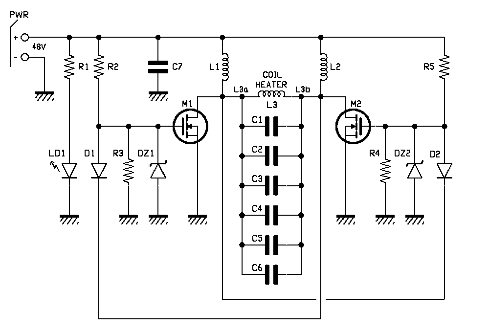
The project utilizes a Royer oscillator topology, a self-oscillating circuit that naturally resonates at the frequency determined by the RLC (Resistor-Inductor-Capacitor) tank circuit. The "Zero Voltage Switching" (ZVS) technique is the key to efficiency here. By timing the switching events so that the MOSFETs transition when the drain-source voltage is nearly zero, the system minimizes power loss and significantly reduces electromagnetic interference.
The Oscillation Sequence
- Initialization: Upon powering the circuit, minor manufacturing discrepancies between the two MOSFETs cause one to conduct slightly before the other.
- Feedback Loop: As the first MOSFET (M1) pulls its drain to ground, the feedback diode (D1) forces the second MOSFET (M2) into a cutoff state.
- Resonant Swing: The RLC tank circuit, composed of the work coil and a bank of high-quality polypropylene capacitors, creates a sinusoidal half-wave.
- Commutation: As the voltage at the drain of M1 returns to zero, the circuit automatically triggers the second MOSFET, repeating the cycle in the opposite phase.
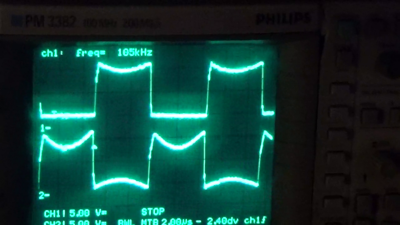
This elegant, push-pull architecture ensures that the switching transistors are never active simultaneously, protecting them from catastrophic short-circuit conditions while sustaining a high-frequency oscillation of approximately 100 kHz.
Supporting Data and Technical Specifications
Achieving 1,000W to 1,500W of output requires robust components capable of handling high thermal and electrical stress.
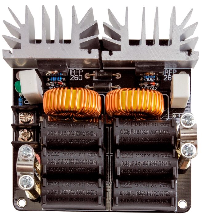
- Switching Components: The system utilizes Infineon IRFP260N MOSFETs. These are chosen for their exceptionally low $R_DS(on)$ (40 mΩ) and high current capacity (50A), which are essential for maintaining efficiency at high power levels.
- Resonant Bank: A total of 2 μF of capacitance is achieved by paralleling six 0.33 μF MKP polypropylene capacitors rated for 630V. Polypropylene is critical here due to its low dielectric loss at high frequencies.
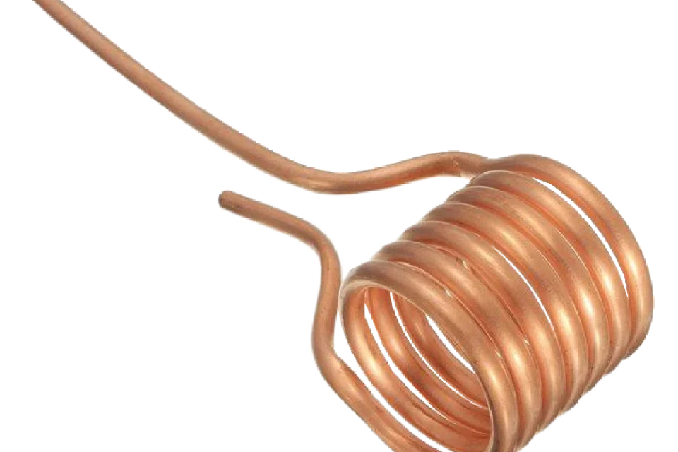
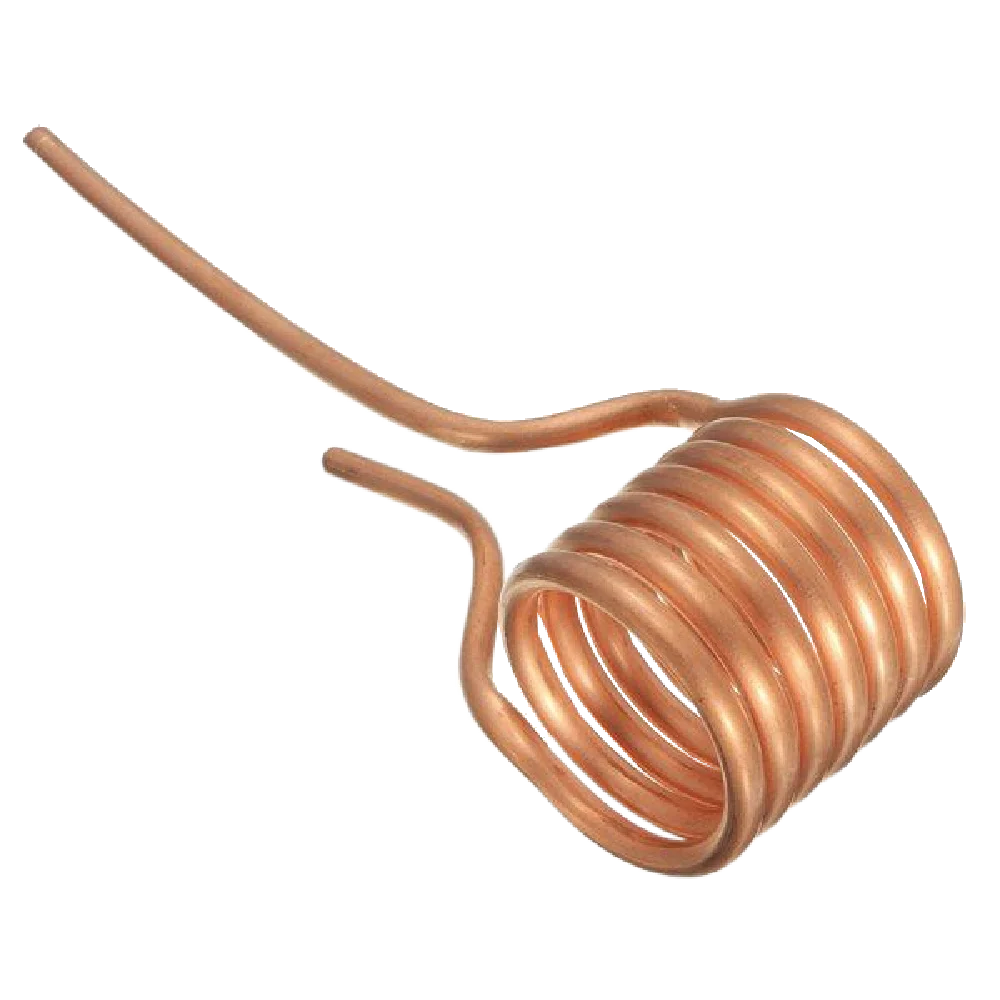
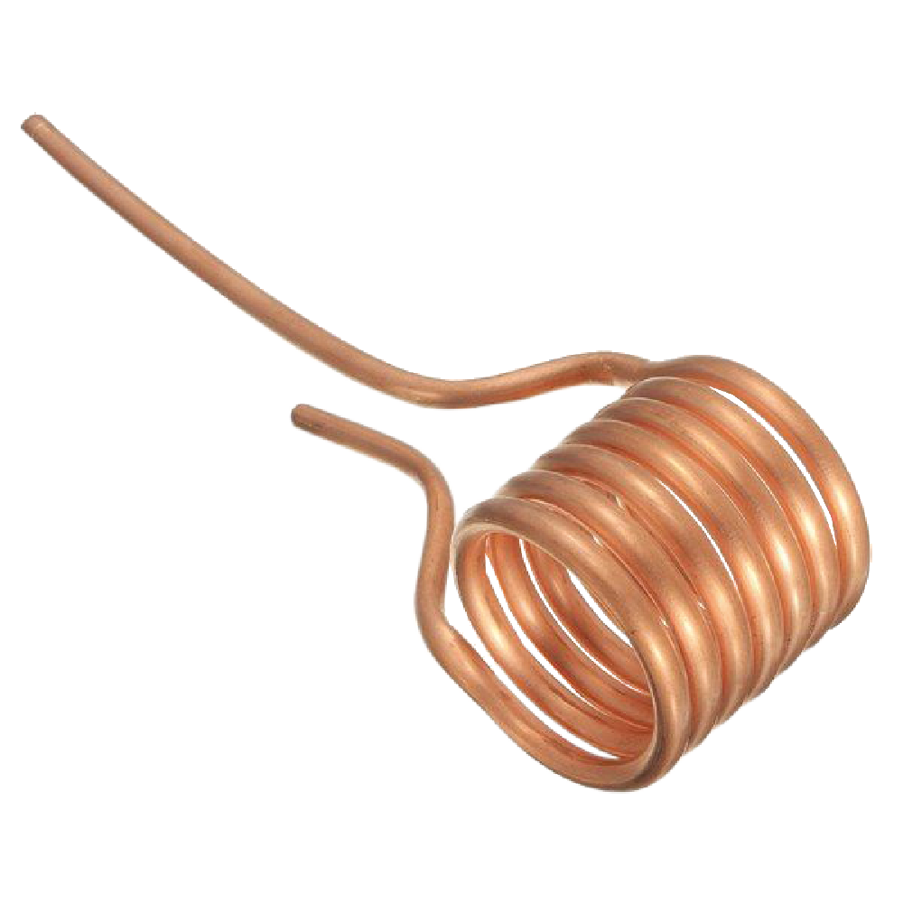
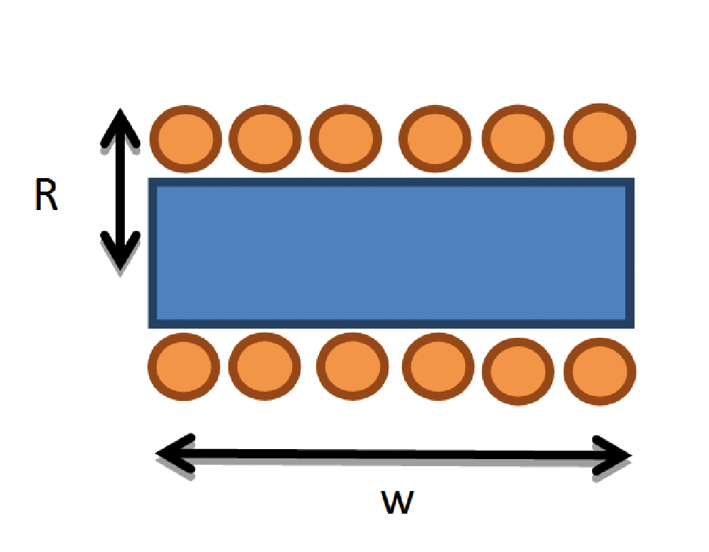
- The Work Coil: The inductor is constructed from 6 turns of 6 mm hollow copper tubing. The use of hollow tubing provides a large surface area to combat the skin effect (where current tends to flow on the outer surface of conductors at high frequencies) and allows for potential liquid cooling in even higher-power configurations.
- Safety and Protection: Protection diodes (MUR420) and Zener-resistor pairs (12V) are integrated to prevent gate overvoltage and provide the necessary speed for fast switching.
Calculated Performance Metrics
Using the physical dimensions of the work coil (Radius R = 2.5 cm, Length w = 7 cm), the theoretical inductance ($L$) is approximately 1.26 μH. Coupled with the 2 μF capacitor bank, the resonant frequency ($f_R$) is calculated as:
$$f_R = frac12pi sqrtLC approx 100.3 text kHz$$
At an input of 48 VDC, the system draws approximately 17A, resulting in a robust magnetic flux density of roughly 10.7 mT (107 gauss) within the coil, sufficient to induce rapid heating in any steel object inserted into the center of the solenoid.
Official Observations and Practical Operation
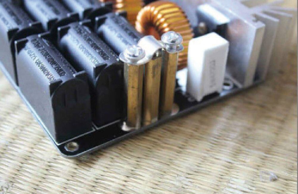
The assembly of the unit is a process that demands meticulous attention to detail. The work coil must be rigidly supported by hexagonal standoffs, and care must be taken to ensure the turns do not touch, as this would short-circuit the turns and shift the resonance frequency, potentially causing instability.
Operational Guidelines
When operating the system, users must adhere to strict safety protocols:
- Power Supply: A dedicated power supply capable of providing 48V at 1,500W is recommended to ensure stability under load.
- Load Introduction: The metallic object should be inserted slowly into the center of the coil, ensuring it never touches the copper tubing.
- Thermal Awareness: The heat generated by the Joule effect is immense. The workpiece will glow yellow-orange within seconds. Users should never touch the coil, the heatsinks, or the workpiece immediately after operation, as the residual heat is significant.
- Device Longevity: It is normal for the work coil to oxidize and darken over time due to repeated high-temperature cycles; this is an aesthetic change that does not impact the system’s performance.
Implications for Future Engineering
The successful deployment of this ZVS induction heater highlights the transition of complex electronic theory into practical, high-power application. Beyond the immediate thrill of melting steel, the implications for this technology are vast.
Induction heating is widely regarded as one of the most efficient methods for industrial thermal processing, offering precise control, localized heating, and rapid response times. By moving away from resistive heating elements, industrial processes can reduce energy waste and improve safety. Furthermore, the principles explored here—specifically wireless power transfer through coupled coils—are the bedrock of modern consumer technologies, such as wireless phone charging and high-efficiency electric vehicle charging stations.
This project serves as a bridge between the classroom and the laboratory. It demystifies the "invisible" fields that govern our world and provides a tangible, powerful demonstration of how human ingenuity can capture and redirect fundamental forces of physics to reshape the material world. As we continue to refine the efficiency of ZVS circuits, we move closer to a future where energy transfer and thermal processing are not only more powerful but significantly more efficient and sustainable.
