

In the world of electronics, stability is the cornerstone of reliability. Whether you are charging a delicate battery chemistry, testing the forward voltage of high-power LEDs, or characterizing the impedance of sensors, the ability to deliver a precise, unvarying current is non-negotiable. While many lab-grade power supplies offer current-limiting features, they often lack the granularity and specialized dual-mode functionality required for specific benchtop tasks.
Enter a sophisticated, DIY-friendly solution: a microcontroller-based, adjustable constant current generator designed around the Microchip PIC16F1765. This project transcends the capabilities of a simple power supply by integrating both constant current sourcing and sinking, coupled with intelligent features like mAh tracking and automatic shutdown.
Main Facts: The Anatomy of the Device
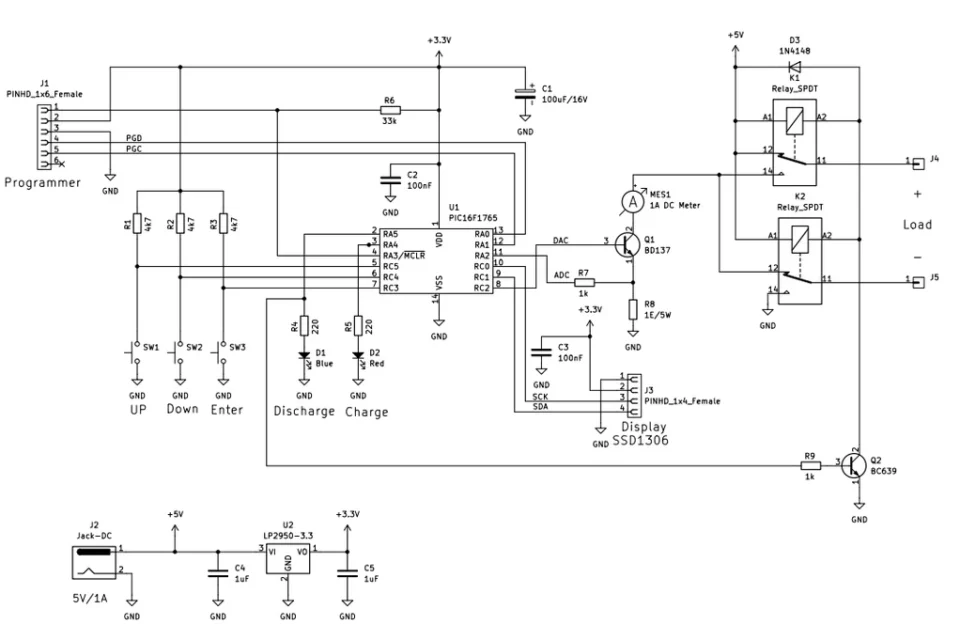
At its core, this project is a digitally controlled analog powerhouse. It allows users to adjust current output from 0 to 1,000 mA with high precision. By combining both sourcing (providing current) and sinking (drawing current) modes, the device acts as both a power supply and an electronic load.
Key technical specifications and features include:
- Controller: PIC16F1765 8-bit microcontroller.
- User Interface: Three-button input (UP, DOWN, ENTER) paired with an SSD1306 OLED display.
- Operational Range: 0 mA to 1,000 mA.
- Advanced Functionality: Integrated timer, mAh capacity calculation, and automated shutdown sequences.
- Calibration: On-board calibration routines to ensure accuracy across the entire 1A range.
- Feedback: Visual status indication via red (source) and blue (sink) LEDs.
This device is not merely a prototype; it is a highly refined tool that bridges the gap between generic hobbyist equipment and specialized lab instrumentation.
Chronology: From Concept to Calibration
The development of this project followed a rigorous engineering path, focusing on iterative improvement and component optimization.
The Design Phase
The project began with the selection of the PIC16F1765. This specific microcontroller was chosen for its unique peripheral set, including an integrated 10-bit Analog-to-Digital Converter (ADC), a Digital-to-Analog Converter (DAC), and a built-in operational amplifier. These internal resources allowed the designer to eliminate several external components, reducing the overall footprint and potential failure points.

The Prototyping Hurdle
During the initial breadboarding phase, the team encountered a significant signal integrity issue. The SSD1306 display, which communicates via the I²C protocol, introduced substantial electrical noise into the system. This noise interfered with the PIC’s delicate analog measurements, leading to erratic current readings.
The solution, arrived at after extensive testing, was to isolate the power rails. By introducing an LP2950 3.3V regulator dedicated specifically to the display and the microcontroller’s communication lines, the team effectively decoupled the digital noise from the analog control loop. This architectural refinement was the "Aha!" moment that ensured the project’s stability.
Assembly and Firmware
Final assembly was split across two distinct boards to manage heat and layout efficiency. The primary board houses the logic and UI, while the secondary board holds the high-current components: the BD137 power transistor, a robust 1Ω power resistor, and the relays responsible for mode switching. The firmware, coded in the JAL programming language, was developed to handle the UI, non-volatile memory storage, and a high-speed 1ms control loop that ensures the current remains rock-steady even as the load fluctuates.
Supporting Data: Why the PIC16F1765?
The efficiency of this device is rooted in the "emitter follower" configuration. By leveraging the PIC16F1765’s internal operational amplifier, the circuit can directly drive the base of the BD137 transistor. This creates a feedback loop where the microcontroller monitors the voltage across the 1Ω resistor—directly proportional to the current flow—and adjusts the DAC output to compensate for any variance.
Power Management and Reliability
The use of High Endurance Flash (HEF) memory within the PIC ensures that user settings, such as calibration offsets and current thresholds, survive power cycles. This is crucial for a tool meant to be used intermittently in a lab environment. The inclusion of an external 5V, 1A power supply ensures that the device has the necessary overhead to deliver its full range of current without sagging under load.
Heat Dissipation
A critical consideration for any current-sinking device is thermal management. The BD137 transistor, when handling currents approaching 1A, dissipates significant power as heat. The project documentation emphasizes that a heat sink is not an optional accessory but a requirement for longevity. Without adequate thermal dissipation, the junction temperature would quickly exceed safe limits, leading to thermal runaway or hardware failure.
Official Insights: The Developer’s Perspective
The developers emphasize that this project is intended to solve a very specific problem: the need for a compact, versatile tool that can handle both the charging of Nickel-Metal Hydride (NiMH) batteries and the controlled discharge of electronic components.

"The ability to calculate mAh during a discharge cycle is a game-changer for makers testing battery capacity," the developers note. "Most generic power supplies provide a constant voltage or a limited current, but they don’t ‘know’ how much energy has been consumed by the load. By integrating a timer and logic for mAh calculation, we have turned a simple current generator into a diagnostic tool."
When asked about the choice of the JAL programming language, the team highlighted its readability and efficiency in managing low-level hardware registers, which is vital when working with the tight, 1ms timing loops required for stable current regulation.
Implications for Makers and Professionals
The implications of this project are twofold. First, it serves as an educational blueprint. By analyzing how the PIC16F1765’s internal DAC/ADC and Op-Amp work in concert, students and hobbyists can gain a deeper understanding of closed-loop control systems.
Second, it provides a high-value utility for the professional bench. In an era where specialized equipment often costs hundreds or thousands of dollars, the ability to construct a high-precision constant current source for a fraction of that cost—using readily available components—is a significant achievement.
Practical Applications
- Battery Management: The device is ideally suited for "forming" cycles on NiMH batteries, where precise, constant current is required to condition the cells.
- LED Characterization: Professionals can use the device to test the brightness vs. current curves of LEDs without the risk of overdriving them.
- Component Stress Testing: The sinking mode allows for the safe discharge of capacitors or the testing of power supply transient responses.
Future Developments
While the current iteration of the device is fully functional, the modular nature of the design invites further innovation. Future iterations could incorporate a USB-serial bridge to log current data directly to a computer, allowing for the generation of discharge graphs in software like Excel or MATLAB. Furthermore, the inclusion of a larger heat sink or an active cooling fan could theoretically push the device beyond the 1A threshold, provided the power supply and current-sensing resistor are scaled accordingly.
In conclusion, this project stands as a testament to the power of thoughtful engineering. By focusing on fundamental principles—noise isolation, precise feedback loops, and robust firmware—the designers have created a tool that is as reliable as it is versatile. For those looking to upgrade their electronics workbench, this adjustable constant current source and sink represents a perfect marriage of form, function, and technical sophistication.
For more information on component sourcing or to view the full schematics and firmware, visit the official project repository or the Open Electronics store for further documentation.