Building a Versatile GSM Remote Control System: An In-Depth Guide to Arduino-Based TDG Emulation (Part 2)
Main Facts: Expanding the Horizons of Cellular Telecontrol
In the rapidly evolving landscape of home automation and industrial remote management, flexibility and modularity remain the ultimate goals for engineers and hobbyists alike. Following the foundational hardware introduction presented last month, this concluding installment explores the comprehensive firmware architecture, configuration strings, and advanced command sets that power a modernized, Arduino-driven clone of the classic TDG133 remote control system.
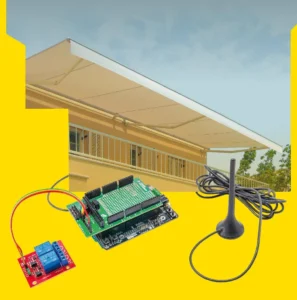
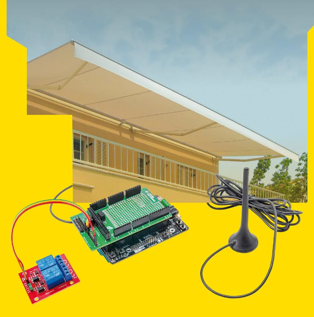
Built around an Arduino Mega 2560 paired with a dedicated GSM/GPRS Shield, this DIY telecontrol solution transcends the rigid limitations of standard commercial units. While the traditional TDG133 features a fixed configuration of two optoisolated voltage inputs and two relay outputs, the Arduino Mega-based architecture scales up effortlessly. By customizing the firmware (GSM_TDG133.ino) and leveraging the microcontroller’s vast array of general-purpose input/output (GPIO) pins, builders can scale the system to handle up to eight digital inputs and eight modular relay outputs.
This second installment provides a granular look into factory parameter management, UART configuration, complex command string syntax, phonebook database operations, input filtering, and event notification structures. Whether deployed for marine bilge monitoring, gate automation, or remote industrial equipment resets, this open-source remote control platform offers enterprise-grade customizability through straightforward SMS text commands or direct serial monitoring.
Chronology and Development Roadmap
The development of this modular GSM remote control system has followed a structured, two-part engineering pipeline designed to ensure seamless hardware integration and robust software reliability.

Phase 1: Hardware Foundation and Baseline Architecture (Issue 231)
- Design Conception: The project originated from the need to replicate and modernize the proven operational profile of the TDG133 remote controller.
- Component Selection: An Arduino Mega 2560 was chosen as the core processing unit due to its extensive I/O capacity and multi-UART support. A compatible GSM Shield was integrated to manage cellular connectivity via AT commands.
- Initial Assembly: Physical stacking of the GSM shield and custom interconnections established a stable 2-input/2-output prototype capable of basic cellular relay switching.
Phase 2: Firmware Integration and Advanced Command Deployment (Current Installment)
- EEPROM and Flash Mapping: Implementation of permanent data storage mechanisms for system parameters, phonebook directories, and localized configuration strings.
- Software UART Configuration: Establishment of reliable serial routing between the ATmega 2560 and the cellular module using Software Serial 1, complete with diagnostic monitoring capabilities.
- Command String Standardization: Translation of legacy TDG133 protocols into an expanded, text- and SMS-compatible command set supporting security passwords, memory mapping, and debouncing filters.
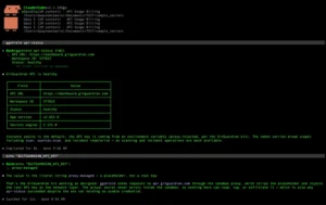
- System Profiling and Testing: Execution of benchmark queries (
REV?,QUAL?,OPER?) to verify hardware handshake integrity with the underlying SIM800C-class GSM engine.
Supporting Data: Comprehensive Command Syntax & System Parameters
Configuring the GSM remote control requires strict adherence to syntax rules. Commands can be dispatched via SMS or through the Arduino IDE Serial Monitor. Below is a detailed breakdown of the primary operational parameters and command strings governed by the firmware.
1. System Security and Password Management
Security is anchored by a numeric-only, five-digit password system (defaulting to 12345).
- Changing the Password:
PWDxxxxx;pwd
(Example:PWD33225;12345updates the password to33225)
2. Phonebook Database Operations
The system accommodates up to 250 memory locations on the SIM card, where numbers stored in slots 1 through 8 maintain administrative and notification privileges, while higher slots facilitate caller-ID gate-opening functions.
- Saving a Number:
NUMx+39nnnnnnnnnnn;text;pwd
(Example:NUM2+393474131177;ROSSI;33225assigns Mr. Rossi to memory slot 2) - Deleting a Number:
NUMx;pwd - Reading Phonebook Subsets (Slots 1–8):
NUM?;pwd - Reading the Entire Phonebook Directory:
ANUM?;pwd - Searching by Contact Name:
FNUM?;text;pwd
3. SMS Memory Maintenance
To prevent SIM card buffer saturation over extended operational lifespans, the firmware includes memory-clearing routines.

- Delete Single SMS:
DSMSx;pwd - Delete All Stored SMS:
DASMS;pwd
4. Input Notifications and Trigger Levels
Digital inputs can be mapped to trigger automated SMS alerts and voice calls (VOC) to the primary administrative contacts stored in the first eight memory locations.
- SMS Notification Toggle:
SMSxxxxxxxx:ON;pwdorSMSxxxxxxxx:OFF;pwd - Voice Call Notification Toggle:
VOCxxxxxxxx:ON;pwdorVOCxxxxxxxx:OFF;pwd - Activation Logic Levels: Inputs can be configured for active HIGH (
A), active LOW (B), or state TOGGLE (V) using theLIVcommand family:
LIVx:A;pwd|LIVx:B;pwd|LIVx:V;pwd
5. Input Debouncing, Inhibition, and Observation Timers
To eliminate false alarms caused by electrical noise or transient environmental fluctuations, the firmware incorporates sophisticated timing controls:
- Inhibition Time (Masking): Ignores subsequent state changes for a specified duration (0–59 minutes) after an initial trigger.
INIx:mm;pwd - Inhibition Override: Forces the system to honor or bypass masking parameters upon rest using
TIZ1x;pwdorTIZ2x;pwd. - Observation Time (Debounce): Requires an input state to remain stable for 1 to 59 seconds before confirming an alarm condition.
OSSx:ss;pwd
6. Custom Alarm Messaging and Output Control
- Alarm Text Customization: Users can assign custom text strings (up to 100 characters, excluding commas and semicolons) to specific input states.
TIN1A:Bilge flood alarm!!;33225 - Repetition Limits: Controls how many times an alarm SMS is dispatched while an input condition persists (0 = none, 99 = infinite).
ALNy:xx;pwd - Relay Management: Controls output states directly, including timed pulse operations ranging from 1 to 59 seconds.
OUTx:ON;pwd|OUTx:OFF;pwd|OUTx:ss;pwd
Official Technical Specifications & Hardware Setup
Proper hardware jumper configuration is critical to establishing stable communication between the Arduino Mega 2560 and the onboard GSM module.
UART and Jumper Configuration
The system relies on Software Serial 1 to manage AT commands while allowing developers to monitor serial traffic in real time.

- Jumpers JP1 through JP7 on the GSM shield must be carefully positioned to pins
1-2to route the UART TX and RX lines correctly. - Developers should consult the configuration table provided in the header of the
Io_GSM.hsource file prior to powering on the assembly.
LED Status Indicators
The GSM shield features diagnostic LEDs driven by the core sketch to provide instant visual feedback on operational status:
- Status LED: Flashes during network registration and remains solid once connected to the cellular provider.
- Net Light: Indicates signal handshake progress and packet transmission states.
- Error/Debug LEDs: Signal UART packet collisions or SIM card initialization failures.
Technical Implications and Future Outlook
The deployment of an Arduino-powered, open-architecture remote control system bridges the gap between expensive, proprietary industrial telecontrol units and simple, unprogrammable consumer smart-plugs.
Advantages of Open-Source Telecontrol
- Scalability: By shifting away from rigid hardware constraints, technicians can scale physical inputs and outputs using standard modular relay boards.
- Cost-Efficiency: Utilizing off-the-shelf components—specifically the Arduino Mega and SIM900/SIM800-class shields—drastically reduces bill-of-materials costs for custom automation projects.
- Firmware Transparency: Complete access to the source code allows advanced users to implement custom encryption, integrate secondary sensor arrays (such as temperature or humidity monitors), or adapt the protocol for IoT platforms via MQTT gateways.
Future Development Vectors
While current limitations—such as the absence of an integrated backup battery for instantaneous power-failure SMS dispatching (PWRF)—highlight minor hardware constraints, the firmware architecture is intentionally forward-compatible. Upcoming revisions are expected to introduce native backup power management, expanded Bluetooth debugging via updated SIM800 variants, and streamlined OTA (Over-The-Air) firmware update protocols.
By mastering the command syntax, EEPROM parameter mapping, and modular I/O mapping outlined in this two-part feature, developers unlock a powerful, highly resilient cellular remote control platform capable of meeting the rigorous demands of modern automated environments.