Precision Power: Engineering a Versatile Constant Current Generator with the PIC16F1765
In the modern laboratory, the ability to maintain a precise, unwavering current—regardless of fluctuations in load resistance—is a fundamental requirement. Whether testing semiconductor behavior, characterizing LEDs, or performing controlled charging cycles for battery chemistry research, a stable current source is indispensable. A recent engineering project has successfully realized a high-performance, dual-mode constant current generator that bridges the gap between sourcing and sinking. Built around the Microchip PIC16F1765 microcontroller, this device offers a compact, programmable, and highly accurate solution for electronics enthusiasts and professionals alike.
Main Facts: The Architecture of Precision
The core of this project lies in its sophisticated control loop. Capable of generating or sinking current from 0 to 1000 mA, the device is far more than a simple power supply; it is a programmable instrument. The system integrates several advanced functionalities, including an onboard timer for mAh calculation, automatic power-off logic to preserve energy and hardware, and a calibration suite to ensure long-term accuracy.
The user interface is purposefully minimalist yet intuitive, utilizing three tactile buttons (UP, DOWN, and ENTER) to navigate menus displayed on a crisp SSD1306 OLED screen. The system operates on a 5V external power supply, capable of sustaining a 1A load, making it a portable yet robust addition to any test bench.
Technical Specifications at a Glance
- Controller: PIC16F1765 (featuring integrated 10-bit ADC/DAC and internal Op-Amp).
- Current Range: 0–1000 mA.
- Modes: Constant Current Source (Sourcing) and Constant Current Sink (Sinking).
- Feedback: SSD1306 OLED display.
- Firmware Language: JAL (Just Another Language).
- Safety Features: Automatic shutdown, current-flow detection, and thermal management via heatsinking.
Chronology: From Concept to Calibration
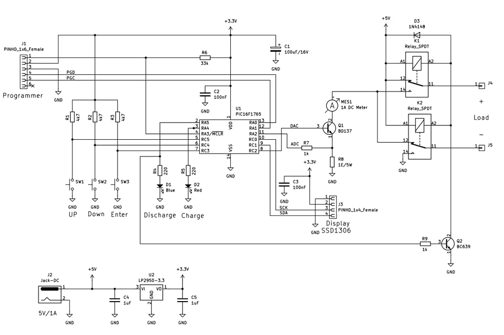
The development of this project followed a rigorous iterative engineering process, starting from the selection of the PIC16F1765. The designers chose this specific microcontroller because it possesses an onboard operational amplifier, which significantly reduces external component count and simplifies the feedback loop required for current control.
The Design Phase
Initial prototypes focused on the emitter-follower configuration using a BD137 power transistor. During the early testing phase, developers encountered significant signal integrity challenges. The I²C bus, responsible for communication between the PIC and the SSD1306 display, proved highly susceptible to noise. This resulted in erratic display behavior and corrupted data packets. The resolution required a refined power management strategy: both the display and the microcontroller were transitioned to a stable 3.3V supply regulated by an LP2950. This decoupling successfully isolated the sensitive digital communication from the high-current power switching, ensuring rock-solid stability.
Assembly and Integration
The physical construction was modularized to accommodate a standard enclosure. The project was divided into two distinct PCBs:

- Control Board: Housing the PIC16F1765, the OLED display, and the user interface buttons.
- Power Board: Containing the BD137 transistor, the primary 1Ω power resistor, and the relay switching network.
The decision to split the boards served both a mechanical purpose—fitting the device into a compact housing—and an electrical one, separating the sensitive logic signals from the thermal and electrical noise of the power stage.
Supporting Data: Why the PIC16F1765?
The selection of the PIC16F1765 is not merely a matter of convenience; it is a deliberate engineering choice to maximize efficiency. The chip’s internal 10-bit DAC allows the firmware to generate an extremely precise reference voltage. This voltage is fed into the internal operational amplifier, which drives the base of the BD137 transistor. By monitoring the voltage drop across the 1Ω shunt resistor, the PIC creates a closed-loop system that adjusts the base drive current every millisecond.
Firmware and Memory Management
The software, written in JAL, is the "brain" of the operation. It handles the PID-like regulation of the current, the interpretation of button presses, and the storage of user-defined settings. To ensure the device remains reliable over years of operation, the developers utilized the High Endurance Flash (HEF) memory. This allows the device to store calibration constants and preferred settings that survive power cycles, ensuring that the tool is ready for use immediately upon startup.
Thermal Considerations
Handling 1000 mA through a BD137 generates significant heat, particularly during discharge cycles (sinking mode). The design mandates the use of an external aluminum heat sink attached to the BD137. During stress tests, this passive cooling was sufficient to keep the junction temperature within safe operating limits, preventing thermal runaway and ensuring the longevity of the transistor.
Official Responses and Practical Application
The versatility of this device is best demonstrated through its real-world performance. During internal demonstrations, the unit was tasked with several key functions:
- Battery Management: The device proved capable of charging NiMH batteries at a constant 200 mA rate, while simultaneously tracking the time and total mAh delivered.
- Controlled Discharge: For capacity testing, the device transitioned to sink mode, pulling 400 mA from the cell until a specific threshold was met, at which point the automatic shutdown feature engaged.
- Calibration: Using an external precision ammeter, the device was calibrated to ensure the 1A output was accurate to within the margin of the 10-bit ADC’s resolution.
According to the design team, the goal was to provide a "maker-friendly" tool that does not sacrifice professional-grade accuracy. By eliminating the need for expensive, bulky laboratory equipment, this project offers a high-value alternative for hobbyists who require precise current control for LED characterization, battery health analysis, or general component testing.

Implications: The Future of Modular Test Equipment
This project serves as a compelling case study for the "build-it-yourself" movement in electronics engineering. By leveraging modern, feature-rich microcontrollers, designers can condense complex, multi-stage circuits into simple, dual-PCB architectures.
Impact on the Maker Community
The reliance on the JAL programming language and the use of widely available components (BD137, SSD1306, PIC16F1765) makes this project highly reproducible. It encourages users to delve into the nuances of analog-to-digital feedback loops, signal noise mitigation, and thermal design. Furthermore, because the source code and design principles are accessible, the community is invited to expand upon the design—perhaps by adding a USB-to-Serial interface for data logging or implementing a higher-resolution DAC for even finer current granularity.
A Compact Solution for Professionals
In professional settings, space is often at a premium. The modular design of this current generator proves that high-performance instrumentation does not require a large rack-mount chassis. As more electronics professionals shift toward agile, desk-side testing, projects like this highlight the potential for custom-built, application-specific tools that outperform general-purpose, off-the-shelf equipment in terms of convenience and task-specific efficiency.
Ultimately, the creation of this adjustable constant current generator is a testament to the power of thoughtful hardware-software integration. By identifying the limitations of standard components—such as I²C bus noise—and addressing them with proper power regulation and logical firmware, the designers have created a reliable, accurate, and highly useful tool that will undoubtedly find a permanent home on many lab benches. Whether for the student learning the basics of power electronics or the engineer needing a quick, stable current source for a prototype, this PIC16F1765-based generator represents the gold standard of modern DIY engineering.