Mastering the MAX7219 LED Matrix with Arduino: A Comprehensive Engineering and Programming Guide
Introduction and Main Facts
For electronics hobbyists, makers, and engineering students stepping into the vast world of microcontroller development, few components captivate the imagination quite like the 8×8 LED matrix. Capable of bringing static text, dynamic numbers, crisp symbols, and fluid animations to life, these compact display modules immediately elevate any project from a simple circuit board to an engaging, interactive device. However, driving an 8×8 LED matrix natively presents a formidable hardware challenge: controlling 64 individual light-emitting diodes requires a massive investment of general-purpose input/output (GPIO) pins—an almost impossible task for microcontrollers with limited pins without dedicated multiplexing hardware.
Enter the MAX7219 integrated circuit, a compact, highly efficient serial input/output common-cathode display driver designed specifically to streamline the management of matrix displays and 7-segment numerical readouts. By handling the complex multiplexing internally, the MAX7219 reduces the required interface down to just three core communication lines, opening up the world of complex visual output to beginner and advanced microcontroller platforms alike.
This comprehensive technical guide explores the architecture of the MAX7219 chip, outlines the essential hardware wiring required to interface it with modern Arduino development boards (including the classic UNO R3 and the contemporary UNO R4 Minima and WiFi), details software implementation using the popular LedControl library, and walks through four progressive practical examples—culminating in a real-time environmental monitoring dashboard utilizing temperature and humidity sensors.
Chronology of Evolution: From Discrete Multiplexing to Integrated Serial Drivers
To fully appreciate the engineering significance of the MAX7219, it is helpful to review the historical evolution of matrix display driving techniques in embedded systems.

- The Era of Discrete Multiplexing (Late 20th Century): Early experimenters attempting to drive 8×8 dot-matrix displays had to rely on discrete components, transistor arrays (such as the ULN2003 or Darlington transistor pairs), and direct GPIO bit-banging from the microcontroller. Updating a display required rapidly cycling through rows and columns at a frequency high enough to trick the human eye via persistence of vision (POV). This approach consumed virtually all processing power and required dozens of external resistors and control lines.
- The Advent of Dedicated Shift Registers and Drivers: As microcontrollers gained popularity, chip manufacturers identified the need for specialized peripheral ICs. The introduction of serial-input, parallel-output shift registers reduced pin counts, but software still bore the burden of multiplexing timing.
- The MAX7219 Revolution: Maxim Integrated introduced the MAX7219 to offload the entire burden of multiplexing, segment decoding, and current regulation from the host processor. By incorporating an internal multiplex scan oscillator, segment drivers, digit drivers, and static RAM to store the 8×8 grid data, the chip transformed matrix programming into a straightforward memory-mapping exercise.
- Modern Module Integration: Today, the MAX7219 is rarely purchased as a bare 24-pin IC for breadboard assembly by hobbyists. Instead, it is mass-produced on ready-to-use breakout modules that bundle the chip, the 8×8 LED matrix (available in various colors such as red, green, or blue), decoupling capacitors, and current-setting resistors onto a single compact PCB with standardized pin headers.
- Compatibility with Contemporary Hardware: While originally designed alongside classic 8-bit AVR boards like the Arduino UNO R3, the MAX7219 and its associated software libraries have seamlessly transitioned to modern 32-bit platforms, such as the Arduino UNO R4 Minima and WiFi, ensuring long-term hardware relevance.
Technical Architecture: Understanding the MAX7219 Chip and Module Wiring
The MAX7219 is packaged in a 24-pin integrated circuit format. Understanding its pinout and internal topology is essential for troubleshooting custom layouts or scaling multi-module display arrays.
Pinout and Hardware Configuration
In an 8×8 LED matrix configuration, the display’s rows are connected to the DIG (Digit) pins of the MAX7219, while the columns are linked to the SEG (Segment) pins.
- Current Regulation (
Iset): The operating current supplied to the LEDs is governed by an external precision resistor connected between theIsetpin and the positive supply rail (VCC). This hardware configuration sets the maximum segment current, protecting the LEDs from thermal runaway. Software brightness control is then handled digitally by modulating the internal pulse-width modulation (PWM) duty cycle across 16 distinct intensity levels. - Serial Interface Pins: Communication between the host microcontroller (e.g., Arduino) and the MAX7219 relies on a synchronous 4-wire serial interface (though only 3 wires are strictly required for write-only operations):
- DIN (Data In): Serial data is shifted into the internal 16-bit shift register on the rising edge of the clock signal.
- CLK (Clock): The synchronization clock supplied by the master controller.
- CS / LOAD (Chip Select / Load): When
CSis pulled low, data is allowed to clock into the internal register. On the rising edge ofCS, the data is latched and executed, updating the display RAM. - DOUT (Data Out): Used exclusively for daisy-chaining multiple modules. The
DOUTpin outputs the data shifted out of the internal register, allowing developers to connect multiple 8×8 matrices in series to construct long, continuous scrolling text banners.
Ready-Made Modules vs. Custom Wiring
For most developers, utilizing pre-assembled modules (Fig. 3) eliminates the complexities of manual decoupling capacitor placement and resistor calculations. These modules feature two distinct sets of pin headers:
- Input Header:
VCC,GND,DIN,CS, andCLK(connected directly to the Arduino). - Output Header:
VCC,GND,DOUT,CS, andCLK(routed to theDINand control lines of subsequent modules in a daisy chain).
Electrically, these modules are fully compatible with both the legacy Arduino UNO R3 and the modern Arduino UNO R4 (Minima and WiFi). The R4 variants retain identical form factors, pin layouts, and operating voltage levels (5V logic), ensuring that existing hardware shields and software libraries function without modification.

Programming Framework and the LedControl Library
While SPI communication with the MAX7219 can be implemented using native Arduino SPI libraries or raw bit-banging, the LedControl library remains the industry standard for simplicity and reliability. It abstracts away the low-level SPI register manipulation, providing an intuitive object-oriented interface.
Core Library Functions and Syntax
-
Initialization:
#include "LedControl.h"
// LedControl(DIN, CLK, CS, number_of_modules)
LedControl lc = LedControl(2, 4, 3, 1);
This instantiates a
LedControlobject (namedlc), mapping data to pin 2, clock to pin 4, chip select to pin 3, and configuring a single module in the chain. -
Power Management (
shutdown):
lc.shutdown(module_number, status);Controls the power state of the MAX7219. Setting
statustofalse(or0) wakes the chip up from its default low-power standby mode into active operation. Setting it totrue(or1) puts the device into shutdown mode. -
Brightness Adjustment (
setIntensity):lc.setIntensity(module_number, intensity);Modulates global display brightness across a range from
0(minimum intensity) to15(maximum intensity). Note that a setting of0dims the LEDs significantly but does not completely extinguish them; total shutdown requires theshutdowncommand. -
Display Clearing (
clearDisplay):
lc.clearDisplay(module_number);Instantly flushes the internal display RAM, turning off all 64 LEDs on the targeted module.
-
Pixel-Level Control (
setLed):lc.setLed(module_number, row, column, state);Manipulates an individual LED at specific coordinates. Rows and columns are indexed from
0to7. The top-left corner corresponds to(0, 0), and the bottom-right corner corresponds to(7, 7). Thestateparameter accepts boolean values (true/1for ON,false/0for OFF). -
Row and Column Manipulation (
setRow/setColumn):
lc.setRow(module_number, row, value);
lc.setColumn(module_number, column, value);
Allows bulk control of an entire row or column by passing an 8-bit binary or hexadecimal byte. For example, passing
B11110000illuminates the first four LEDs in the specified row.
Practical Implementation: Four Progressive Arduino Sketches
To demonstrate the versatility of the MAX7219 display system, we examine four progressive programming examples, moving from basic geometric sweeps to sensor-driven data visualization.
Example 1: Sequential Sweeps and Dynamic Intensity Modulation
The first implementation exercises the hardware by iterating through geometric patterns. The sketch sequentially illuminates rows from top to bottom, columns from left to right, rows in reverse, and columns in reverse.
Following these linear sweeps, the sketch transitions to a symmetric inward-filling pattern, activating rows in pairs from the center outward (4-5, then 3-6, 2-7, and 1-8). During this final phase, the software dynamically modulates the global brightness, ramping intensity down smoothly from level 10 to level 2 to create a fading visual effect.

Example 2: Analog Potentiometer Bar Graph
Bridging the gap between input and output, the second sketch integrates an analog potentiometer connected to analog input pin A5. By reading the analog voltage (scaling from 0V to 5V), the microcontroller maps the input value to the vertical resolution of the LED matrix. As the user twists the potentiometer, rows light up progressively from the bottom upward, transforming the 8×8 matrix into a real-time analog bar-graph display.
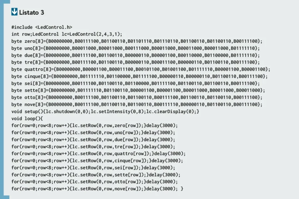
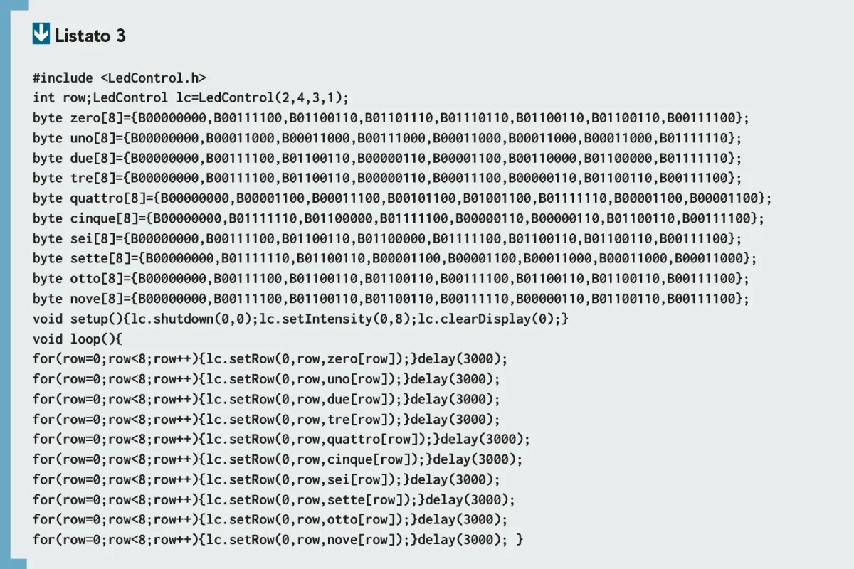
Example 3: Utilizing Arrays for Character Rendering
Directly calling setLed for complex graphics is inefficient. A more scalable approach utilizes byte arrays, where each element in an 8-byte array represents a horizontal row on the matrix.
For instance, to configure a split display where the top four rows are off and the bottom four rows are fully illuminated, developers define:
byte array[8] =
  B00000000,
  B00000000,
  B00000000,
  B00000000,
  B11111111,
  B11111111,
  B11111111,
  B11111111
;
Rendering this array to the display requires a simple iterative loop:

for (int row = 0; row < 8; row++)
  lc.setRow(0, row, array[row]);

delay(3000);
For generating custom graphical assets, characters, and numeric symbols without manual binary calculation, developers can leverage online utility tools such as the LED Matrix Editor. Example 3 builds upon this array-based architecture to render the full sequence of numerical digits from 0 to 9 in smooth succession.
Example 4: Real-Time Environmental Threshold Monitor
The final application demonstrates a complete Internet of Things (IoT) / environmental monitoring dashboard. This sketch monitors ambient temperature and relative humidity and presents warning indicators directly on the LED matrix.
- Display Partitioning: The 8×8 grid is split vertically. Columns
0,1, and2are dedicated to temperature data, while columns5,6, and7display humidity metrics. - Visual Indicators: In the upper horizontal section (rows
0,1, and2), static charactersT(Temperature) andU(Humidity) are rendered. In the lower section (rows4through7), progressive rows light up to indicate threshold breaches. As environmental readings climb past pre-programmed limits, additional rows illuminate dynamically, starting from row7upward. - Sensor Hardware Integration: Data acquisition is handled by the HTS221 capacitive digital sensor, integrated into the STMicroelectronics IKS01A3 expansion board mounted directly atop the Arduino UNO board (Fig. 5). For hobbyists lacking this specific evaluation board, the code can be easily adapted to support more common environmental sensors, such as the DHT11 or DHT22, by modifying the data-reading functions in the software.
Supporting Data and Technical Specifications
| Parameter | Specification | Notes |
|---|---|---|
| Operating Voltage | 4.7V – 5.5V (Typically 5V DC) | Compatible with standard Arduino 5V rails |
| Interface Protocol | 4-Wire Serial (SPI-compatible) | DIN, DOUT, CLK, CS/LOAD |
| Max Clock Frequency | 10 MHz | Supports rapid data updates and fluid animations |
| Display Architecture | Common-Cathode 8×8 Matrix | Multiplexed internally by the MAX7219 IC |
| Intensity Control | 16-step Digital Brightness Control | Modulated via internal PWM register |
| Standby Current | < 150 µA | Ultra-low power consumption in shutdown mode |
Official Responses and Engineering Best Practices
When integrating MAX7219 modules into hardware prototypes, hardware design engineers and application developers emphasize several critical best practices to ensure long-term stability and optimal performance:
- Power Supply Decoupling: Due to the simultaneous switching of multiple high-current LEDs, transient voltage spikes can occur on the
VCCrail. Manufacturers recommend placing a 0.1 µF ceramic capacitor directly across theVCCandGNDpins of each MAX7219 module, particularly when daisy-chaining multiple displays. - Current Limiting Resistors: While most commercial breakout modules include a pre-installed resistor (typically 10kΩ) connected to the
Isetpin, developers building custom PCBs must verify this value to prevent exceeding the maximum allowable forward current of the specific LED matrix being driven. - Signal Integrity in Daisy Chains: When linking multiple modules together for scrolling marquee applications, long jumper wires on the
CLKandCSlines can pick up electromagnetic interference (EMI), leading to corrupted display frames. Keeping inter-module wiring as short as possible mitigates signal degradation.
Implications and Future Outlook
The accessibility of the MAX7219 driver chip has fundamentally transformed how embedded systems developers approach low-resolution visual output. By democratizing access to complex matrix displays, it bridges the gap between raw hardware manipulation and high-level software abstraction.

Whether deployed in educational environments to teach basic programming loops and array manipulation, or utilized in professional prototyping environments for real-time sensor dashboards, industrial status panels, and wearable tech, the MAX7219 remains an essential tool in the modern maker’s toolkit. As microcontrollers continue to evolve toward faster processing speeds and wireless connectivity, simple, robust peripheral drivers like the MAX7219 ensure that hardware projects can continue to "speak with light" clearly, dynamically, and effectively.