Building an Advanced GSM-Powered Remote Control: Emulating the TDG Series with Arduino and the SIMCom GSM Shield
Main Facts
The landscape of DIY and professional embedded electronics has taken a significant leap forward with the release of a comprehensive practical application utilizing the SIMCom, QUECTEL, and FIBOCOM GSM/GPRS shields. Engineers and hobbyists can now replicate and even expand upon the legendary TDG133 bidirectional GSM remote control system. Originally introduced in 2010, the TDG133 standard is renowned for its ability to manage two relay outputs and two voltage-level inputs remotely via SMS and voice commands.
By anchoring this new project to the robust Arduino Mega 2560 (or its derivative, the Fishino Mega 2560) and mating it with a custom-engineered expansion board dubbed the Shield Telecontrollo, developers gain access to an industrial-grade cellular remote control platform. The architecture cleverly utilizes the ATmega 2560’s onboard EEPROM for system parameters and alarm strings, while offloading the expansive phonebook database—supporting up to 208 authorized phone numbers—directly to the SIM card’s native memory.
This project bridges legacy telecontrol reliability with modern cellular modules, offering both serial monitor configuration and SMS-driven control options.

Chronology of Development and Implementation
The evolution of this project follows a carefully structured developmental pipeline, transitioning from foundational cellular integration to advanced dual-sketch firmware design.
Phase 1: Hardware Foundation and Shield Integration
The journey began with the release of universal GSM/GPRS shields designed for seamless Arduino integration. Recognizing the need for a practical, real-world application, developers targeted the feature set of the classic TDG133. Because standard microcontroller boards lack the necessary I/O availability and memory overhead, the Arduino Mega 2560 was chosen as the core processing unit. The creation of the Shield Telecontrollo provided the physical routing layer, mapping ports PA0–7 for digital outputs and PL0–7 for digital inputs, alongside general-purpose LED indicators.
Phase 2: Firmware Structuring and Dual-Sketch Compilation
To streamline setup without cluttering runtime execution, developers organized the firmware using an innovative compilation directive: #define WRITE_DEFAULT_DATA_EEPROM.

- During Setup Mode: When this directive is active, the compiler builds the setup routine, injecting factory parameters, system passwords, and default alarm strings into the ATmega 2560’s EEPROM.
- During Operational Mode: When the directive is commented out, the compiler skips the setup allocation and builds the core remote control application, executing the main operational loops and parsing incoming communication strings.
Phase 3: Automated SIM Registration and Steady-State Transition
Upon initial boot, the system checks the SIM card’s phonebook. If no administrative number is found in the primary memory slot, the system enters an interactive registration window. Visualized by alternating flashes on yellow LEDs LD6 and LD7, the device waits up to five minutes for an incoming voice call from any number. The first caller is automatically registered as the "ADMIN." Once this handshake completes, the system enters a stable operational state, processing periodic AT commands and monitoring real-time digital inputs.
Supporting Data and Hardware Architecture
The technical execution of the GSM remote control relies on a meticulously planned hardware topology and memory map.
Hardware Block Diagram and Shield Telecontrollo Layout
The physical hardware layout is divided into dedicated functional zones:

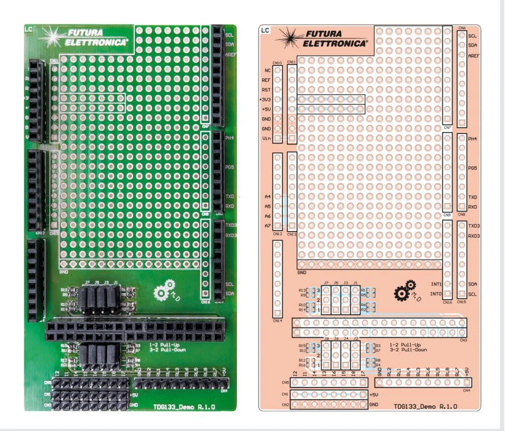
- Digital Inputs: Accommodates up to eight inputs via port PL0–7. Jumpers (J1–8) allow users to select active-high (10kΩ pull-down resistor via position 2-3) or active-low (10kΩ pull-up resistor via position 1-2) configurations. Connector CN5 handles trigger wiring, while CN1 and CN2 distribute +5Vdc and GND rails for simulation purposes.
- Digital Outputs: Port PA0–7 routes signals to connector CN4, supplying power and control lines capable of driving up to eight auxiliary relay boards (though default firmware actively manages two inputs and two outputs out-of-the-box).
- Prototyping Area: A dedicated onboard breadboarding section featuring a standard 2.54mm pitch grid provides over 315 potential-free single pads, accompanied by dedicated +3.3V, +5V, and GND power rails for custom circuitry additions.
EEPROM Memory Map and SIM Allocation
Because the ATmega 2560’s EEPROM, while substantial, cannot house upwards of 200 telephone numbers alongside system configurations, a hybrid memory strategy was adopted:
- EEPROM (0x0000 to 0x0FFF): Stores critical runtime variables, GSM library PIN/PUK requirements, system passwords (starting at address
0x0050), and customizable SMS alarm strings for input triggers. - SIM Card Memory: Acts as the primary database for authorized user directories. Up to 208 phone numbers—including those designated exclusively for gate-opening functions—are stored here alongside name descriptions, mirroring a standard mobile phone contact list.
| Memory Region | Address Range / Source | Primary Function |
|---|---|---|
| System Parameters | EEPROM (0x0000 – 0x004F) |
GSM library configuration, PIN/PUK codes |
| System Password | EEPROM (0x0050 onwards) |
Authentication for SMS/Serial commands |
| Alarm Text Strings | EEPROM (Allocated Blocks) | Custom messages dispatched during input state changes |
| User Phonebook | SIM Card Native Memory | Stores up to 208 authorized phone numbers and contact labels |
Official Responses and Firmware Mechanics
Behind the user-facing features lies a sophisticated software loop governed by modular C++ architecture. The codebase is broken down into specific files to maintain clean syntax and logical separation:
GSM_TDG133.ino: The main entry point containing compilation directives, global variables, and core logic._SetupEeprom.ino: Houses the EEPROM memory mapping and factory default parameter flashing routines.
The Main Execution Loop (void loop())
Once initialization clears via the void setup() function—which initializes the GSM library, pre-loads EEPROM variables, and sets default input states—the microcontroller enters an infinite execution loop. The core processing architecture relies heavily on dedicated state machines:

- UART Communication Management (
Gsm.ExecuteUartState();): Operates continuously outside conditional blocks to maintain uninterrupted serial communication synchronization between the Arduino Mega and the onboard GSM module. - GSM Initialization Check (
Gsm.GsmFlag.Bit.GsmInitInProgress): Uses anif-elseconditional structure. During startup, it runsGsm.InitGsmSendCmd()andGsm.InitGsmWaitAnswer(). Once initialization successfully concludes, the system transitions to theelseblock, activating continuous UART reading (Gsm.UartContinuouslyRead()), unsolicited code processing (Gsm.ProcessUnsolicitedCode()), and steady-state command parsing. - Background AT Command Polling: Under normal steady-state operation, the device continuously cycles through general-purpose AT commands at one-second intervals to query module status, signal strength, and network registration. These can be instantaneously interrupted by high-priority event flags, such as an input alarm trigger.
- Generic AT Commands: Frequently polled queries to check network health and signal quality.
- Specific AT Commands: Triggered conditionally in response to incoming SMS strings, serial monitor instructions, or state changes on the digital input lines.
Implications and Future Outlook
The deployment of this open-source GSM remote control shield architecture carries significant implications for industrial automation, smart-home retrofitting, and remote telemetry applications.
By leveraging widely available Arduino hardware paired with robust cellular shields, engineers can deploy cost-effective, highly customizable remote monitoring stations without relying on proprietary, closed-source industrial gateways. The capability to handle dual monostable/bistable relay outputs, monitor optoisolated voltage inputs, and manage up to 200+ gate-opener numbers transforms a simple hobbyist microcontroller into a serious contender for commercial remote management tasks.
What Lies Ahead
In the upcoming and final installment of this technical series, developers will dive deeper into advanced programming nuances, exploring the exact command syntaxes required for remote configuration, reviewing detailed SMS parsing strings, and decoding the diagnostic LED blink patterns featured on the GSM Shield. As makers continue to expand the firmware beyond its initial two-input/two-output constraints to fully utilize the eight available hardware lines, the potential for scalable, cellular-backed automation remains virtually limitless.