Harnessing the Invisible: Building a 1,000W ZVS Induction Heater
The modern world is saturated with invisible electromagnetic fields. From the hum of power distribution lines and the ubiquitous reach of radio transmitters to the high-frequency bursts of mobile networks, we exist in a constant state of exposure to non-ionizing radiation. While most of these fields remain unnoticed, their latent power is immense. The microwave oven, a staple of every kitchen, serves as a testament to this, using electromagnetic energy to excite water molecules and generate heat. But what happens when we push this technology beyond culinary tasks? What happens when we harness these fields to force metal into incandescence?
This article explores the technical architecture and assembly of a 1,000W Zero Voltage Switching (ZVS) induction heater—a project that transforms electrical energy into intense localized heat through the principles of magnetic induction, eddy currents, and the Joule effect.
Main Facts: The Physics of Induction
At the heart of this project lies the ZVS resonant circuit. To understand its power, one must first understand the fundamental physical interactions at play.
Magnetic Induction and Eddy Currents
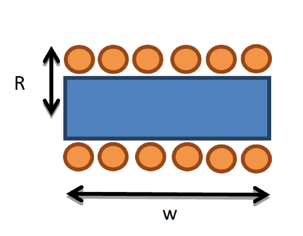
The system operates similarly to a transformer. The primary winding is a high-current copper coil, and the secondary winding is the conductive material placed inside it. When an alternating current flows through the coil, it generates a rapidly oscillating magnetic field. According to Faraday’s Law of Induction, this time-varying flux induces an electromotive force (EMF) within any conductive material inside the field.
This EMF drives the formation of "Eddy currents"—swirling loops of electrical current trapped within the material. Because the material possesses inherent electrical resistance, these eddy currents dissipate energy in the form of heat, a phenomenon known as the Joule effect. In ferromagnetic materials, this process is even more efficient, as the material’s magnetic permeability concentrates the flux, leading to rapid, high-intensity heating.
The ZVS Advantage
Traditional switching power converters suffer from "switching losses"—energy wasted every time a transistor transitions from an "on" state to an "off" state due to the overlap of high voltage and high current. ZVS, or Zero Voltage Switching, mitigates this by timing the switching transitions to occur when the voltage across the semiconductor is nearly zero. This dramatically increases efficiency, reduces thermal stress on the components, and minimizes electromagnetic interference, allowing for a compact, 1,000W (up to 1,500W) system.
Chronology of Development: From Concept to Circuit
The development of this project followed a rigorous path of engineering, starting from theoretical oscillation to the physical implementation of the Royer topology.
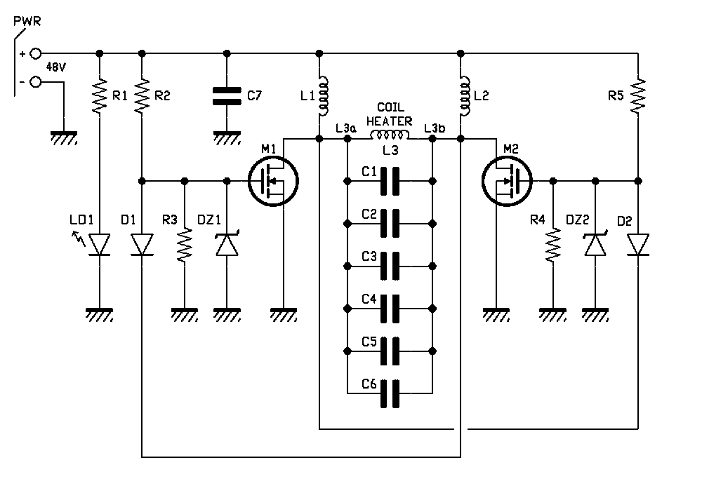
- Oscillator Selection: The choice of a Royer-style oscillator was driven by the need for self-resonance. Unlike external clock-driven circuits, the Royer oscillator naturally finds the resonance frequency of the RLC tank circuit, ensuring that the system always operates at its most efficient frequency.
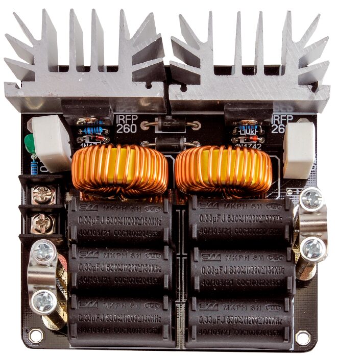
- MOSFET Integration: The selection of the Infineon IRFP260N MOSFETs was critical. With an $R_DS(on)$ of only 40 mΩ and a 50A drain current capacity, these components are optimized for high-power switching.
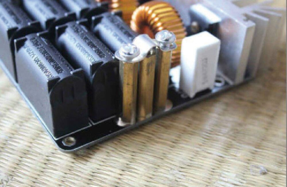
- Resonant Tank Optimization: The team determined that a 2 μF capacitance—comprised of six 0.33 μF MKP polypropylene capacitors—provided the ideal balance between stability and resonant power at the 100 kHz frequency range.
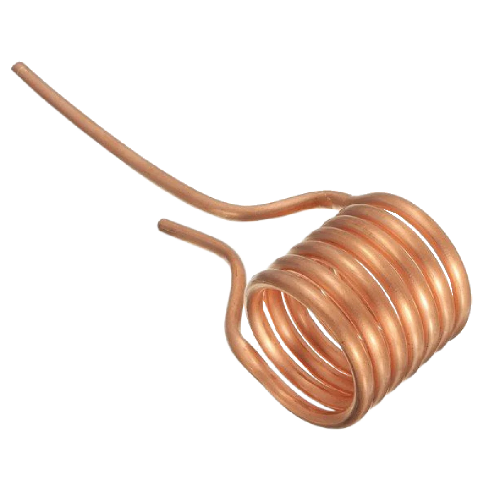
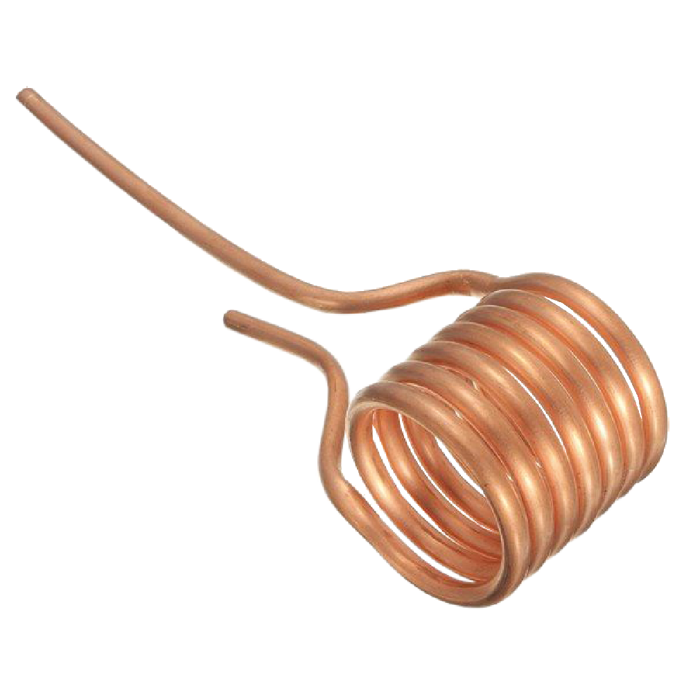
- Coil Fabrication: The work coil was engineered as a 6-turn, hollow copper tube. This specific geometry was chosen to handle the massive 100A RMS current while providing the structural integrity required to contain the magnetic flux within a compact volume.
Supporting Data: Technical Specifications and Performance
The performance of this system is defined by its ability to maintain a stable, high-frequency magnetic field. Below are the core metrics observed during testing.
Key Operational Metrics
- Input Voltage: 48 VDC.
- Operating Frequency: Approximately 100.3 kHz.
- Maximum Power Consumption: Up to 1,500W under load.
- Magnetic Flux Density: Calculated at 10.7 mT (107 gauss) within the coil.
- Switching Topology: Push-pull ZVS using IRFP260N MOSFETs.
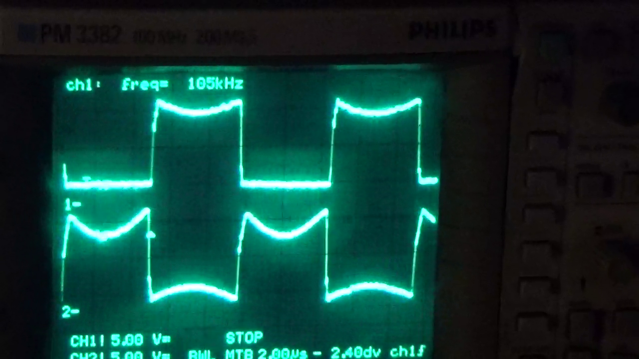
Waveform Analysis
Oscilloscope readings confirm the efficiency of the design. The gate-source voltages of the two MOSFETs (M1 and M2) operate in perfect antiphase. This timing is essential; if both MOSFETs were to conduct simultaneously, the resulting short circuit would cause catastrophic failure of the transistors. The feedback diodes (MUR420) ensure that the gate voltage is pulled to ground immediately upon the turn-off cycle, preventing any "shoot-through" current.
Official Recommendations: Safety and Assembly
Because this device generates extreme heat and utilizes high-current electrical components, strict adherence to safety protocols is mandatory.
Assembly Precautions
- Coil Integrity: The turns of the copper tubing must remain isolated. Bare copper in contact will cause a short, changing the inductance and destabilizing the resonance.
- Current Handling: Use high-quality, thick-gauge wiring to connect the power supply to the terminal block. With currents reaching 17A at 48V, thin wiring will act as a resistor, causing dangerous voltage drops and overheating.
- Component Cooling: While the MOSFETs are designed for efficiency, the sheer power involved necessitates robust heatsinks. Ensure the air flow is not obstructed.
Operating Safety
The system produces a magnetic field strong enough to heat a steel bolt to incandescence in seconds. Never attempt to touch the workpiece while the unit is active, or immediately after it has been removed from the coil. Always utilize insulated pliers. Furthermore, because of the high-frequency emissions, sensitive electronics (like smartphones or medical devices) should be kept at a safe distance during operation to prevent electromagnetic interference.
Implications: The Future of Induction Technology
The ZVS induction heater is more than a tool for melting metal; it is a gateway into understanding power electronics and resonant energy transfer.
Industrial and Academic Utility
Beyond hobbyist applications, the principles used here are the foundation of modern high-efficiency industrial heating. From metal hardening in automotive manufacturing to the sophisticated brazing of vacuum-sealed components, induction heating is favored for its cleanliness, precision, and speed.
Pedagogical Value
For students and enthusiasts, this project bridges the gap between abstract textbook physics and tangible engineering. It teaches:
- Power Electronics: Understanding switching losses and the benefit of ZVS.
- Electromagnetics: Visualizing flux density and the interaction of magnetic fields with conductive matter.
- Circuit Design: The importance of layout, parasitic inductance, and component selection (such as the choice of polypropylene capacitors for high-frequency current handling).
Conclusion
As we continue to push the boundaries of what is possible with power electronics, the ZVS induction heater stands as a robust, scalable, and fascinating project. It serves as a reminder that the invisible forces surrounding us are not merely background noise—they are tools that, when properly harnessed, allow us to manipulate the physical state of matter. Whether you are a seasoned engineer or an electronics student, the construction of this device offers a profound look at the efficiency of modern switching technology and the raw, transformative power of the electromagnetic spectrum.
Proceed with caution, respect the current, and enjoy the process of turning electricity into visible, radiant heat.