Precision Power Control: Building a Versatile Constant Current Source and Sink with the PIC16F1765
In the world of electronics engineering and DIY instrumentation, the ability to maintain a steady, predictable current is a foundational requirement. Whether testing delicate semiconductor components, characterizing battery performance, or driving high-power LEDs, a stable current source is an indispensable laboratory asset. Bridging the gap between commercial-grade precision and accessible hobbyist projects, a new development utilizing the Microchip PIC16F1765 microcontroller offers a robust solution: a dual-mode constant current generator capable of both sourcing and sinking current up to 1000 mA.
Main Facts: A Dual-Mode Power Solution
The project introduces an adjustable constant current generator designed to maintain a stable output regardless of load fluctuations. Unlike conventional power supplies that prioritize voltage regulation, this device focuses on maintaining a rigid current flow, a critical requirement for electrochemical processes and thermal testing.
Key technical specifications of the device include:
- Current Range: 0 to 1000 mA, fully adjustable.
- Operational Versatility: Integrated current sourcing and sinking capabilities.
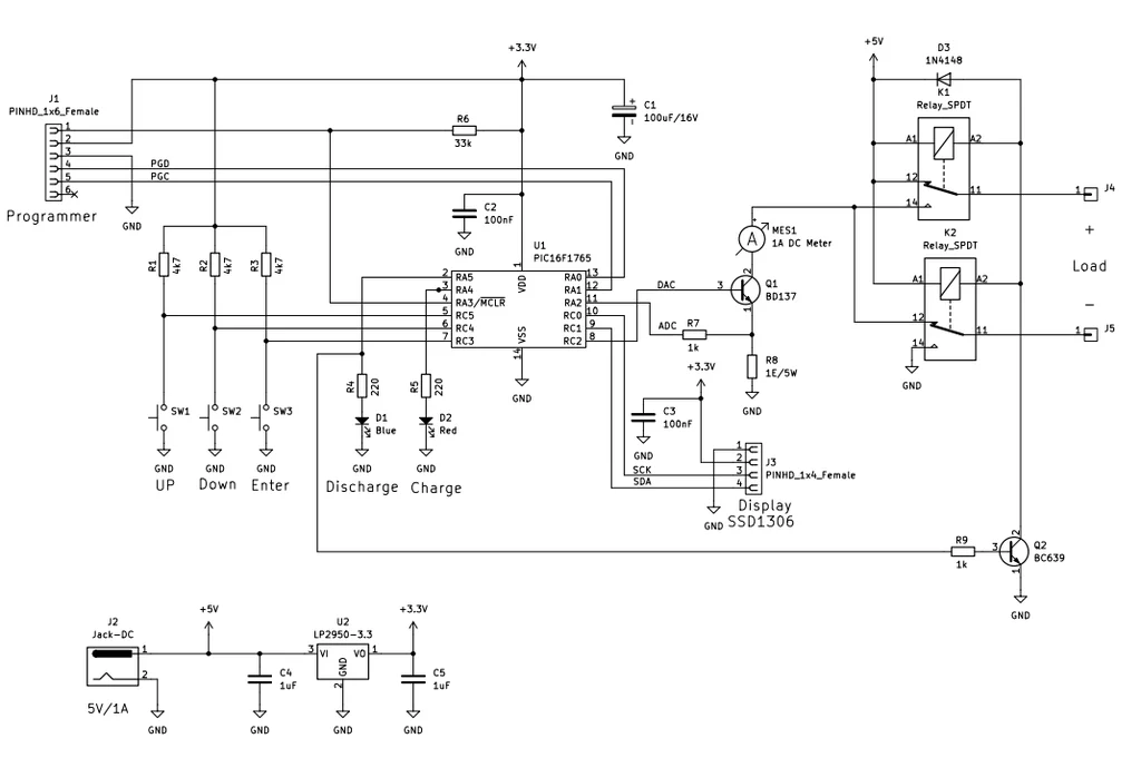
- Microcontroller Architecture: Built around the PIC16F1765, utilizing its internal 10-bit Analog-to-Digital Converters (ADC), Digital-to-Analog Converters (DAC), and internal operational amplifiers.
- User Interface: Three-button input (UP, DOWN, ENTER) paired with an SSD1306 OLED display for real-time monitoring.
- Advanced Features: Integrated timer, mAh (milliamp-hour) capacity calculation, automatic shutdown protocols, and software-based calibration.
- Power Requirements: External 5 V supply capable of sustaining 1 A continuous current.
By integrating both sourcing and sinking modes, the device allows for comprehensive battery testing—charging via the source mode and discharging via the sink mode—providing a compact, all-in-one solution for energy storage analysis.
Chronology of Development: From Concept to Calibration
The development cycle of this project highlights the iterative nature of embedded systems design. Initially conceived as a simple current source, the project evolved as the developers recognized the utility of adding "sink" functionality for battery discharge testing.

- Selection Phase: The PIC16F1765 was chosen primarily for its high level of integration. By leveraging the chip’s internal op-amps, the design eliminates the need for external analog circuitry, reducing footprint and component count.
- Prototyping and Thermal Management: Early prototypes revealed that the BD137 power transistor, while efficient, generated significant heat at the upper end of the 1000 mA range. This necessitated a modular board approach: one board for the logic/control interface and a secondary "power" board equipped with the BD137 and a substantial heat sink.
- Debugging the I²C Bus: A major technical hurdle encountered during development was signal integrity. The SSD1306 display module introduced electrical noise onto the I²C bus, leading to intermittent display corruption and logic errors. The solution involved stabilizing the power delivery to both the display and the microcontroller via an LP2950 3.3 V regulator, which effectively decoupled the sensitive logic from the power-hungry peripheral.
- Firmware Refinement: The firmware was written in the JAL programming language. The development team prioritized high-frequency control, implementing a 1 ms update loop to ensure the current remains stable despite transient load changes. The utilization of High Endurance Flash (HEF) ensures that calibration data and user settings remain preserved through power cycles.
Supporting Data: Engineering Precision and Stability
The efficacy of the device lies in its sophisticated control loop. The PIC16F1765’s internal DAC provides a reference voltage that, when fed into the op-amp configuration, dictates the bias of the BD137 transistor. By monitoring the voltage drop across a precision 1 Ω power resistor, the microcontroller creates a closed-loop feedback system.
Thermal Considerations
Power dissipation in the BD137 is a function of the voltage drop across the transistor and the current flowing through it. At 1 A, the power dissipation can reach several watts, making the inclusion of an aluminum heat sink non-negotiable. During testing, it was observed that without adequate cooling, the current output would drift as the transistor’s junction temperature rose, affecting the gate-emitter characteristics.
Firmware Logic
The firmware manages the system state through a state machine:
- Idle: The device monitors input for setpoint changes.
- Active: The PID-like control loop calculates the required DAC value every 1 ms.
- Safety/Shutdown: If current flow drops to zero or a timer threshold is reached, the device triggers an automatic shutdown to protect both the DUT (Device Under Test) and the internal circuitry.
Official Technical Perspectives
In discussions regarding the project’s design philosophy, the developers emphasized the importance of calibration. "A constant current source is only as good as its feedback loop," noted one lead engineer. By incorporating a software-based calibration routine, users can connect a high-precision external ammeter to the output terminals, allow the system to step through various current levels, and save the correction offsets directly into the microcontroller’s memory.
Furthermore, the choice of the JAL (Just Another Language) compiler for this PIC architecture allows for highly efficient code that fits within the microcontroller’s limited memory while maintaining the speed necessary for real-time adjustments. The ability to distinguish between "Source" and "Sink" modes via LED indicators (Red for source, Blue for sink) provides an essential visual cue that prevents accidental reverse-polarity errors during operation.

Implications for Makers and Professionals
The implications of this project are significant for both hobbyist makers and laboratory technicians.
Democratizing Laboratory Tools
Professional-grade constant current loads and sources often cost hundreds, if not thousands, of dollars. By utilizing a common, low-cost microcontroller and standard discrete components like the BD137, this project lowers the barrier to entry for high-precision electronics testing. It empowers makers to perform rigorous battery capacity testing—a task usually reserved for expensive smart chargers.
Versatility in Education
The project serves as a comprehensive case study for engineering students. It demonstrates the practical application of:
- Closed-loop feedback control: Understanding how ADC/DAC pairs can replace traditional analog components.
- Signal Integrity: Learning to troubleshoot I²C bus noise in mixed-signal designs.
- Thermal Management: Designing for physical hardware limitations in power electronics.
Future Extensibility
While the current iteration is robust, the design is inherently extensible. Future upgrades could include:
- Logging Capabilities: Adding an SD card module or a serial-to-USB bridge to log discharge curves to a PC.
- Increased Power Density: Scaling the power stage with an array of transistors to support currents beyond 1 A.
- Connectivity: Integrating Bluetooth or Wi-Fi to allow remote monitoring and configuration of the current settings.
Conclusion
The adjustable constant current generator based on the PIC16F1765 is a testament to the power of thoughtful, integrated design. By solving the dual challenges of thermal management and signal noise, the developers have created a reliable, accurate, and highly functional tool. For those involved in battery management systems, LED driver testing, or general electronic repair, this device offers a professional-grade capability that is both affordable to build and easy to maintain. As modern electronics continue to rely on precise power delivery, tools like this will remain essential in the technician’s arsenal, proving that high performance does not always require a high price tag.