Building a Smart Touch-Activated Electronic Door Lock with the Arduino UNO R4 WiFi
By the Tech & Hardware Desk
Published: September 2026
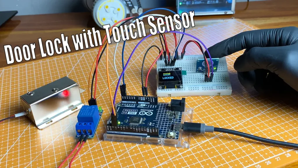
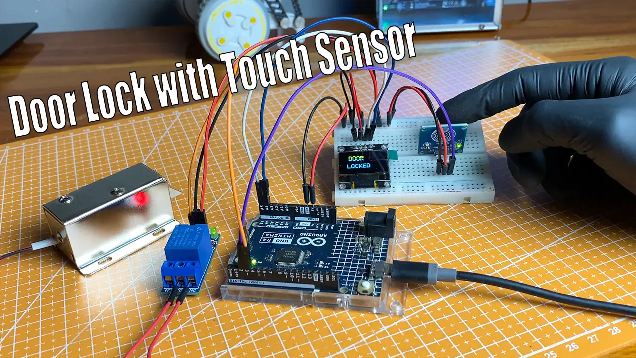
In the rapidly evolving landscape of smart home automation and DIY electronics, access control systems have shifted from being expensive, proprietary installations to accessible, open-source projects. A newly detailed open-source project demonstrates how makers, hobbyists, and engineering students can construct a reliable, touch-activated electronic door lock using modern hardware components. Centered around the powerful Arduino UNO R4 WiFi, this prototype combines a capacitive touch sensor, a solid-state relay module, a 128×64 pixel OLED display, and a 12VDC solenoid lock to create a fully functional, automated security gateway.
While the core mechanics of the system are deceptively simple—touch the sensor, open the door for five seconds, and let gravity or spring-tension re-secure the latch—the project serves as a foundational blueprint. It illustrates how low-voltage microcontrollers can safely interface with higher-power electromechanical actuators, paving the way for advanced, connected residential security solutions.
Main Facts: Core Architecture and Component Breakdown
The architecture of this touch-activated electronic door lock relies on a clear separation of logic control and power delivery. At its heart is the Arduino UNO R4 WiFi, a microcontroller board that not only coordinates the input/output (I/O) events of the system but also provides a built-in pathway for future internet-of-things (IoT) expansion.
Key Hardware Elements
- Arduino UNO R4 WiFi: Serving as the central processing unit, this board reads digital input signals from the touch sensor, updates the user interface on the visual display, and toggles the relay state.
- Capacitive Touch Sensor: Acting as the primary user interface, this sensor detects human contact. Unlike mechanical pushbuttons, capacitive sensors offer a sleek, flush-mount aesthetic that can be hidden behind non-conductive panels like wood or acrylic.
- Relay Module: This is a critical safety component. The Arduino operates on a 5-volt logic level, whereas the solenoid door lock requires a 12VDC power supply to actuate its heavy internal plunger. The relay uses an isolated electromagnetic switch to let the low-power Arduino trigger the high-power lock without risking electrical damage to the microcontroller.
- 128×64 Pixel OLED Display: Communicating via the Inter-Integrated Circuit (I2C) protocol, this screen provides real-time visual feedback. It keeps users informed of the system’s operational states, cycling through startup screens, "Locked" statuses, and "Unlocked" countdowns.
- Solenoid Door Lock: An electromechanical device that retracts its bolt when energized with 12 volts, allowing the door to open freely. Once power is cut, an internal spring returns the bolt to its resting, locked position.
Chronology: The Engineering Workflow and Operational Lifecycle
Developing and deploying an embedded hardware project of this nature follows a precise engineering lifecycle, moving from theoretical design to benchtop prototyping and live execution.
Phase 1: Conceptualization and Component Sourcing
The project originated from a need to demystify commercial electronic access control. The development workflow began with gathering the essential components: an Arduino UNO R4 WiFi, an SSD1306-driven OLED display, a single-channel relay, a touch sensor, a 12V solenoid lock, a breadboard, and a universal acrylic mounting plate to keep the wiring orderly.
Phase 2: Breadboard Assembly and Circuit Integration
During the prototyping phase, makers assembled the circuit using 15 cm male-to-female jumper wires to interconnect the modules without immediate soldering.
- The Power Divide: The 12V power supply rail was dedicated strictly to the solenoid lock through the relay’s common (COM) and normally open (NO) terminals.
- The Logic Layer: The Arduino’s 5V and GND pins powered the logic side of the relay, the OLED display, and the touch sensor.
- Signal Routing: The touch sensor’s digital output pin was routed to one of the Arduino’s digital input pins, establishing a high-low polling state.
Phase 3: Firmware Development and Library Integration
Writing the firmware required the Arduino IDE and several standardized graphics and display libraries, specifically Adafruit_GFX and Adafruit_SSD1306. The code structure was engineered around a continuous loop checking for an interrupt or a high-state change from the touch sensor.
Phase 4: System Operation and Cycling
Once powered on, the system enters its active operational lifecycle, which unfolds in four distinct stages:
- Startup: The OLED display initializes via I2C, displaying a system-ready boot message.
- Waiting (Locked): The display reads "LOCKED" while the solenoid remains unpowered, keeping the door securely bolted.
- Trigger & Unlock: A user touches the capacitive sensor. The sensor sends a HIGH signal to the Arduino, which instantaneously trips the relay. The 12V circuit closes, retracting the solenoid bolt. The OLED display shifts to an "UNLOCKED" status screen.
- Relock Countdown: An internal software timer initiates a 5-second delay. Once elapsed, the Arduino cuts power to the relay, the solenoid springs back into the locked position, and the OLED reverts to the "LOCKED" state.
Supporting Data: Specifications and Technical Parameters
To fully appreciate the design constraints and capabilities of this smart door lock prototype, it is helpful to examine the technical specifications governing its components:
| Component | Technical Specification / Parameter | Function in System |
|---|---|---|
| Microcontroller | Arduino UNO R4 WiFi (5V Logic, ARM Cortex-M4) | Central processing, Wi-Fi connectivity, I/O management |
| Display | 128×64 Pixel OLED (SSD1306 Driver, I2C Interface) | Real-time visual status reporting |
| Actuator | 12VDC Solenoid Lock | Physical door restraint and release mechanism |
| Switching Unit | Single-Channel Optocoupled Relay Module | Electrical isolation between 5V logic and 12V power |
| Input Device | Capacitive Touch Sensor Module | Touch-sensitive user authentication trigger |
| Unlock Duration | Software-defined (Default: 5,000 milliseconds) | Adjustable window for manual door opening |
The utilization of I2C for the OLED display is particularly efficient, requiring only four wires (VCC, GND, SCL, SDA), which leaves the Arduino’s digital and analog pins free for additional sensors or expansion modules. Furthermore, the inclusion of the Arduino UNO R4 WiFi’s native wireless capabilities means that the hardware specifications far exceed the basic requirements of a standalone touch lock, leaving ample room for network-based telemetry.
Official Responses and Creator Insights from the Maker Community
The project, originally documented and shared via prominent maker educational platforms like Sritu Hobby, has drawn considerable attention from hobbyist communities and embedded systems educators. According to project curators and community maintainers, the primary goal of this design is to strip away the unnecessary complexity often found in commercial smart home hubs.
Demystifying Access Control
Makers behind the design emphasize that modern security systems often appear as "black boxes" to consumers. By utilizing transparent, open-source code and modular off-the-shelf components, builders can demystify how electronic access control functions.
"The philosophy behind this build is rooted in radical accessibility," notes technical commentary from the original project release. "By demonstrating that a secure, automated physical barrier can be constructed with fewer than six core components, we empower students and novices to take control of their own hardware learning journey rather than relying on closed-source consumer appliances."
Furthermore, educators have praised the project for highlighting the crucial engineering concept of electrical isolation. Many beginner electronics projects fail or suffer permanent damage because novices attempt to drive inductive loads—like motors and solenoids—directly from microcontrollers. By spotlighting the relay module as an indispensable bridge, the project serves as an effective teaching tool for circuit protection.
Implications: Scalability, Security, and the Future of DIY Smart Homes
While the current iteration of the touch-activated door lock functions effectively as a localized benchtop prototype, its broader implications point toward the future of scalable, modular home automation.
Expanding the Prototype into a Comprehensive Ecosystem
Because the base architecture utilizes the Arduino UNO R4 WiFi, builders are not permanently tethered to a simple touch sensor. The code and hardware layout are intentionally modular, allowing for seamless upgrades:
- Biometric and Keypad Integration: Builders can easily integrate a 3×4 matrix keypad for PIN-based entry or an RC522 RFID reader for badge-based access control, running parallel to or replacing the touch sensor.
- Remote IoT Control: Leveraging the UNO R4’s onboard Wi-Fi module, developers can transition the lock from a purely local device into an internet-connected node. This enables remote unlocking via web dashboards, smartphone applications, or MQTT protocols.
- Audit Logging: With the addition of a Real-Time Clock (RTC) module and an SD card breakout board, the system could log every instance of a touch activation, recording precise timestamps for security audits.
Security Considerations for Real-World Deployment
While educational prototypes provide immense value for learning, transitioning a breadboard-based project to a front-door deployment requires careful engineering considerations. Capacitive touch sensors, while aesthetically pleasing, can occasionally be susceptible to false triggers from moisture, heavy electromagnetic interference, or electrostatic discharge (ESD).
To adapt this prototype for robust, real-world residential security, engineers recommend transitioning from temporary breadboards and jumper wires to a custom printed circuit board (PCB) soldered connections, and weather-sealed enclosures. Additionally, incorporating physical failsafes—such as a concealed mechanical key override—ensures that users will not be locked out in the event of a power failure or microcontroller crash.
Conclusion
The Arduino UNO R4 WiFi touch-activated electronic door lock successfully bridges the gap between theoretical microcontrol programming and practical electromechanical engineering. By keeping the component count low, the firmware transparent, and the design open-source, the project delivers a functional security asset while providing an ideal launchpad for advanced IoT home automation endeavors. Whether built as a weekend learning exercise or expanded into a fully networked smart lock, it stands as a testament to the power and flexibility of modern maker technology.