Precision in Every Ampere: Engineering a Versatile Constant Current Generator with the PIC16F1765
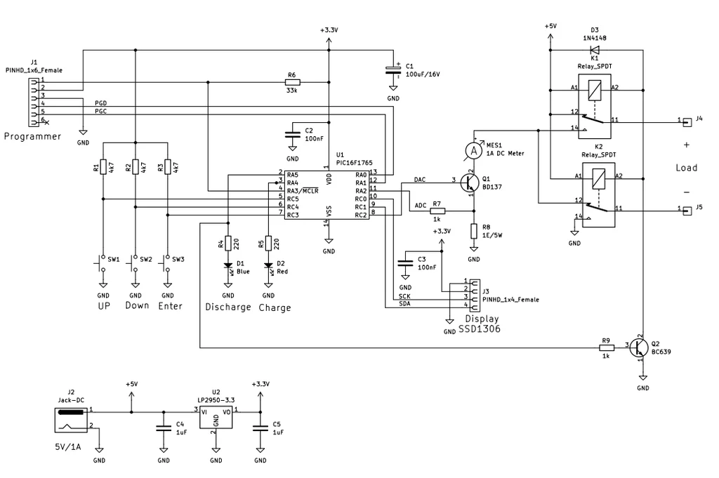
In the realm of electronics, the ability to control current with surgical precision is not merely a convenience; it is a fundamental requirement for component testing, battery management, and sensitive circuit characterization. Whether one is characterizing the forward voltage of an LED, testing a power transistor, or performing a controlled discharge of a NiMH battery, a stable current source—and in many cases, a sink—is indispensable.
A recently developed open-source project, centered around the Microchip PIC16F1765 microcontroller, offers a sophisticated yet accessible solution for makers and laboratory professionals alike. By integrating both constant current sourcing and sinking capabilities into a single, compact device, this project redefines the utility of the benchtop current generator, offering adjustable current control from 0 to 1000 mA with high-resolution feedback.
Main Facts: The Architecture of Precision
The core of this project lies in its intelligent utilization of the PIC16F1765’s internal hardware. Unlike general-purpose microcontrollers that might require a plethora of external peripheral chips, the PIC16F1765 features an onboard 10-bit Analog-to-Digital Converter (ADC), a Digital-to-Analog Converter (DAC), and—most crucially—an integrated operational amplifier.
By configuring the internal op-amp in an emitter follower setup to drive a BD137 power transistor, the system achieves a highly stable, linear control loop. The device is designed to provide a steady output regardless of load fluctuations, a feat accomplished through real-time adjustment firmware running at a 1 kHz update rate.
Key technical specifications include:
- Current Range: 0 mA to 1000 mA (adjustable).
- Operating Modes: Constant Current Source and Constant Current Sink.
- Control Interface: 3-button tactile interface (UP, DOWN, ENTER) paired with an SSD1306 OLED display.
- Ancillary Features: Integrated timer, mAh capacity tracking, and automatic power-down sequences.
- Firmware Foundation: Developed using the JAL (Just Another Language) programming language, utilizing High Endurance Flash (HEF) for reliable, long-term storage of user settings.
Chronology: The Development Lifecycle
The evolution of this project from a conceptual requirement to a functional bench tool provides a fascinating look into the iterative nature of modern electronic engineering.
Phase 1: Conceptualization and Component Selection
The project began with the need for a compact, battery-friendly testing tool. The PIC16F1765 was selected due to its specialized "Intelligent Analog" features. The initial design focus was on the feedback loop—ensuring that the DAC output could accurately modulate the base of the BD137 transistor to maintain a constant current across the 1 Ω power resistor.

Phase 2: The Prototyping Hurdles
During the initial breadboarding phase, developers encountered a significant challenge: signal integrity. When the SSD1306 OLED display was connected, the I²C communication bus generated electrical noise that interfered with the PIC’s ADC readings. This noise rendered the current control erratic, as the reference signal became "jittery."
Phase 3: The Refinement Strategy
The resolution of the noise issue marked a turning point in the project’s stability. By implementing a dedicated LP2950 3.3 V regulator to independently power the SSD1306 display and the microcontroller, the I²C bus was isolated from the primary power fluctuations of the load. This change not only eliminated data corruption but also improved the overall linearity of the current output.
Phase 4: Final Assembly and Firmware Optimization
The final hardware design was split across two boards: one dedicated to the "brain" (microcontroller and UI) and the other to the "muscle" (power transistor, current-sense resistor, and relay logic). Firmware optimization focused on the 1 ms interrupt loop, ensuring that the current remained steady even during rapid load changes.
Supporting Data: Why Current Sinking Matters
In many testing environments, a "current source" is only half the equation. A constant current sink is equally vital, particularly when testing power supplies, voltage regulators, or performing capacity tests on rechargeable cells.
The ability to "sink" current allows the device to act as an electronic load. By drawing a controlled amount of current from a source, the user can measure how that source performs under stress. The integrated mAh calculation feature is a direct result of this, enabling the user to monitor how much energy a battery has delivered during a discharge cycle.
The implementation of the BD137 transistor in the design is worth noting. As an NPN power transistor, it is ideal for this application, provided it is managed correctly. Given that the device handles up to 1 A, thermal management is a critical data point. The inclusion of a robust heat sink is not optional; it is a fundamental requirement to prevent thermal runaway. When operating at the maximum 1 A limit, the power dissipation across the transistor can be significant, and the system relies on the physical properties of the heat sink to maintain the integrity of the control loop.
Official Responses and Practical Applications
The project has garnered significant interest within the maker community, particularly for its practical demonstration of firmware-hardware integration.

Professional Perspectives
Industry professionals have noted that while high-end laboratory power supplies are ubiquitous, they are often bulky and prohibitively expensive for simple, repetitive testing tasks. This project fills the "middle-ground" gap—a tool that is more capable than a simple resistor-based test rig, yet more affordable and customizable than a professional-grade electronic load.
Practical Use Cases
- NiMH Battery Charging: The device can be set to provide a specific, constant current, while the integrated timer ensures the charging cycle is terminated safely, preventing overcharging.
- LED Characterization: By sweeping the current from 0 to 1000 mA, engineers can observe the change in light output and forward voltage, a standard procedure for LED binning and quality control.
- Component Burn-in: Running a component at its maximum rated current for an extended period is a standard stress-test procedure. The stability of this PIC-based generator makes it ideal for such long-duration tasks.
Implications: The Future of Modular Bench Tools
The success of this PIC16F1765-based generator highlights a broader trend in electronics: the democratization of high-precision instrumentation. As microcontrollers become more capable, the need for external, discrete analog circuitry decreases.
The Shift Toward "Intelligent" Hardware
The use of the PIC’s internal DAC to drive the transistor loop demonstrates that we are moving away from monolithic, black-box test equipment toward transparent, open-source designs. Because the code is written in JAL and the hardware is modular, a user can modify the firmware to add features such as:
- PC Connectivity: Adding a USB-to-Serial bridge to log data directly to a spreadsheet.
- Pulse-Width Modulation (PWM) Control: Adapting the firmware to provide pulsed current instead of constant current for specific testing protocols.
- Expanded Calibration Routines: Using the existing calibration feature to account for different resistor tolerances in the field.
A Sustainable Approach to Engineering
By utilizing "High Endurance Flash" (HEF) memory, the device is built to handle the constant read/write cycles associated with changing settings, saving configurations, and logging data. This speaks to a design philosophy that prioritizes longevity. In a world of disposable consumer electronics, a tool that is repairable, re-programmable, and documented in an open format offers an sustainable alternative for both the hobbyist and the professional lab.
Final Verdict
The combination of the PIC16F1765’s native analog peripherals, the robust control offered by the BD137 transistor, and the user-friendly interface makes this project a standout achievement. It provides a blueprint for how complex electrical problems can be solved through thoughtful integration of software and hardware. Whether you are a student looking to understand the fundamentals of current regulation or a professional in need of a custom testing jig, this project offers a reliable, scalable, and deeply educational platform.
As the electronics landscape continues to evolve, projects like this serve as a reminder that the most effective solutions are often those that leverage the power of the components already at our fingertips, refined through careful engineering and a commitment to precision.