Precision Power: Engineering an Advanced Microcontroller-Based Constant Current Source and Sink
In the world of electronics, the ability to maintain a steady, unyielding flow of electricity is not merely a luxury—it is a fundamental requirement for testing, charging, and characterizing components. Whether one is evaluating the health of a battery cell or ensuring the longevity of high-brightness LEDs, an adjustable constant current generator is an indispensable asset. A recent project, centered around the Microchip PIC16F1765 microcontroller, pushes the boundaries of this essential tool by integrating both current sourcing and sinking capabilities into a single, compact, and highly precise device.
This article explores the technical architecture, development hurdles, and practical utility of this versatile instrument, providing a deep dive for makers, engineers, and hobbyists alike.
Main Facts: The Architecture of Precision
At its core, this project solves a classic engineering dilemma: how to maintain a stable current regardless of load fluctuations. By leveraging the advanced features of the PIC16F1765—a chip specifically designed for intelligent analog applications—the system achieves a controllable current range from 0 to 1000 mA.
The device is not merely a static power source; it is an intelligent, user-interactive system. Key features that distinguish this unit from standard lab equipment include:
- Dual-Mode Operation: Seamless switching between constant current sourcing (delivering power) and constant current sinking (drawing power).
- Integrated Analytics: A built-in timer that tracks activity, allowing for the automatic calculation of milliamp-hours (mAh), a vital metric for battery capacity testing.
- Automated Intelligence: Automatic shutdown sequences trigger when no current is detected, preserving the longevity of the device and the components being tested.
- Calibration Protocols: A streamlined user interface allows for field calibration, ensuring the accuracy of the current output against a reference ammeter.
The user interface is facilitated by a minimalist three-button control scheme (UP, DOWN, ENTER), with real-time feedback displayed on a crisp SSD1306 OLED screen.
Chronology of Development: From Concept to Circuit
The development of this project followed a systematic path, reflecting the iterative nature of modern embedded design.
Phase 1: Silicon Selection
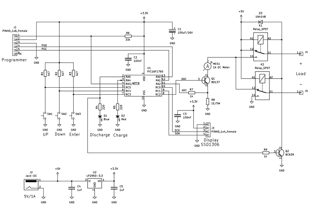
The design began with the selection of the PIC16F1765. This microcontroller was chosen for its onboard high-resolution 10-bit Analog-to-Digital Converter (ADC) and Digital-to-Analog Converter (DAC). Crucially, the chip includes an integrated operational amplifier that allows for a direct, low-latency interface with the BD137 transistor in an emitter-follower configuration. This setup provides the necessary stability to maintain constant current, even as the load changes.

Phase 2: Solving the Noise Floor
During the prototype phase, the engineering team encountered a significant obstacle: intermittent data corruption on the I²C bus. As the SSD1306 display communicated with the microcontroller, the high-frequency switching and noise coupling threatened to destabilize the system.
The team successfully mitigated this by implementing a dedicated power management strategy. By routing both the display and the PIC16F1765 through an LP2950 3.3 V regulator, they effectively isolated the sensitive digital logic from voltage ripples. This stabilization ensured that the I²C signals remained clean and reliable, even at high update rates.
Phase 3: Assembly and Hardware Partitioning
To accommodate the physical constraints of an enclosure, the hardware was split across two distinct boards. One board manages the "brain"—the microcontroller and the OLED interface—while the second board handles the "muscle"—the power-switching stage. This includes the BD137 transistor, a robust 1 Ω power resistor, and the relays required for mode switching. A vital final step was the addition of a heat sink to the BD137, which is necessary to manage the thermal load during 1000 mA operation.
Supporting Data: Firmware and Logic
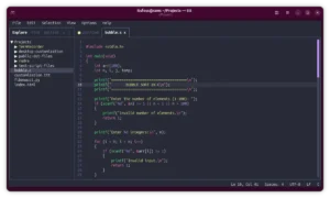
The sophistication of the device lies largely in its firmware, written in the JAL (Just Another Language) programming language. The firmware operates on a 1-millisecond update cycle, ensuring that the control loop is fast enough to react to any transient changes in load.
Memory and Reliability
The design utilizes the microcontroller’s High Endurance Flash (HEF) to store user settings. This ensures that calibration data and mode preferences are retained even after a total power loss. The use of non-volatile memory is a significant design choice, as it transforms the device from a mere test rig into a persistent tool that remembers its last state, facilitating rapid deployment in repetitive testing scenarios.
Logic Flow
The software handles a complex set of tasks:
- UI Management: Debouncing the buttons and updating the OLED interface.
- Control Loop: Adjusting the DAC output to maintain a constant current via the transistor.
- Calculation Engine: Monitoring the timer and current flow to derive mAh, critical for NiMH battery discharge tests.
- LED Feedback: Visual status updates—Red for sourcing, Blue for sinking—providing immediate diagnostic clarity for the operator.
Official Perspective and Implementation
According to the project documentation, the device’s capability to handle both sourcing and sinking makes it uniquely suited for battery chemistry analysis. For instance, in a demonstration, the device was configured to charge NiMH batteries at a steady 200 mA, and subsequently discharge them at 400 mA. By measuring the time taken for the voltage to drop to a predefined threshold, the system automatically calculates the total capacity of the cell.

This dual-mode approach is often missing in low-cost electronics kits, which typically provide only a source or a load, but rarely both in a calibrated, user-programmable package. The project’s reliance on the PIC16F1765’s internal op-amp also highlights a growing trend in engineering: utilizing peripheral-rich microcontrollers to reduce component count, minimize PCB footprint, and improve overall system reliability.
Implications for the Maker Community
The release of this project has significant implications for the broader maker and electronics professional community.
Bridging the Gap
For professionals, this device serves as a "field-ready" tool for troubleshooting. Its compact size allows it to be easily transported to job sites, providing a lab-grade constant current source in an environment where massive benchtop power supplies are impractical.
For hobbyists and students, the project acts as a masterclass in mixed-signal design. It teaches the importance of:
- Thermal Management: Understanding how to calculate and dissipate heat from power transistors.
- Signal Integrity: Learning how to decouple digital noise from sensitive analog control loops.
- Data Persistence: Implementing HEF to create user-friendly, "smart" devices.
A Foundation for Future Innovation
The open nature of this design invites further modification. Because the firmware is modular, users can adapt the code to support different communication protocols, such as adding a serial interface to log data directly to a computer, or increasing the resolution of the current steps for ultra-fine testing. The integration of an external ammeter for calibration further proves that the designer prioritized accuracy over mere convenience, ensuring that the tool remains useful for serious electronics work.
Conclusion
The PIC16F1765-based constant current source and sink stands as a testament to the power of well-integrated firmware and efficient hardware design. By successfully solving the problems of noise, heat, and precise control, this project offers a robust, affordable, and highly capable instrument for anyone involved in modern electronics. As the complexity of modern consumer electronics continues to grow, tools that offer this level of precision and versatility are becoming increasingly essential to the standard maker’s toolkit. Whether you are characterizing a new sensor or reviving old battery packs, this device provides the steady, reliable hand required to get the job done.