Harnessing the Invisible: Building a 1,000W ZVS Induction Heater
Introduction: The Hidden Power of Electromagnetic Fields
We live in an age defined by the invisible. Our modern existence is saturated with electromagnetic waves—ripples of energy flowing from power distribution networks, cellular base stations, radio transmitters, and the ubiquitous gadgets in our pockets. Most of the time, this ambient radiation is benign, detectable only by the faint crackle of a mobile phone placed too close to a speaker. Yet, there is a boundary where these invisible fields transition from ambient background noise into a potent, concentrated force capable of bending matter to its will.
In professional electronics, this transition is mastered through induction. We are all familiar with the modern induction cooktop—a marvel of efficiency that boils water without heating the stove surface itself. But what happens when we push this technology beyond the domestic kitchen? Can we create a field powerful enough to bring steel to incandescence in mere seconds? The answer is a resounding yes. By utilizing a Zero Voltage Switching (ZVS) resonant circuit, we can harness the principles of magnetic induction, eddy currents, and the Joule effect to melt metals with surgical precision.
The Core Principles: Physics in Action
To understand this 1,000W project, one must look at the trio of physical laws that govern it.
1. Magnetic Induction (Faraday’s Law)
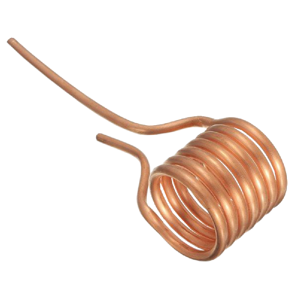
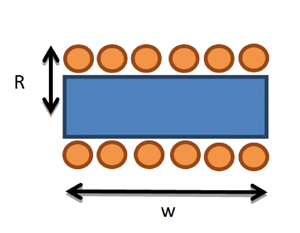
At the heart of the system is a copper coil—the "work coil"—through which a high-frequency alternating current flows. According to Faraday’s law, this time-varying current creates a rapidly oscillating magnetic field. When a conductive object is placed within this field, the magnetic flux lines intersect the material, inducing an electromotive force (EMF).
2. Eddy Currents
The induced EMF does not sit idle; it forces electrons to swirl within the conductive material. These circular, vortex-like patterns are known as "Eddy currents." In traditional transformer design, these are usually parasitic losses to be mitigated. However, in this induction heating project, we specifically engineer the circuit to maximize these currents.
3. The Joule Effect
As these massive currents force their way through the resistance of the metal object, they generate heat, much like the filament of an incandescent bulb or the heating element of a toaster. This energy conversion—from electromagnetic field to thermal energy—is the engine that allows us to reach temperatures capable of melting steel.
Technical Chronology: From Concept to Resonance
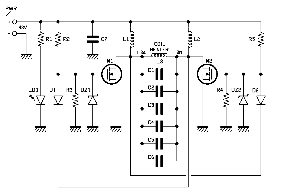
The design of this system relies on the Royer Oscillator, a self-oscillating RLC (Resistor-Inductor-Capacitor) circuit.
Phase 1: The Oscillatory Start
Upon applying power, the circuit enters a state of natural resonance. Because no two components are perfectly identical, slight manufacturing variances ensure that one MOSFET (M1 or M2) conducts slightly before the other. This initial imbalance triggers the self-oscillation process.
Phase 2: The Switching Mechanism
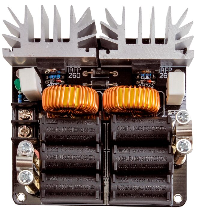
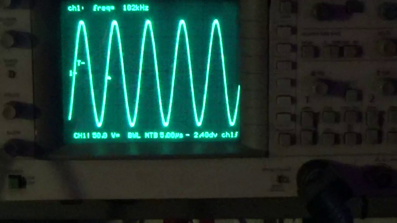
The circuit functions as a push-pull converter. When M1 is active, its drain is pulled to ground, forcing M2 to cut off via the feedback diode D1. The resonant tank circuit then creates a sinusoidal half-wave. As the voltage returns to zero, the roles swap, and M2 turns on while M1 turns off. This ensures that the MOSFETs always switch at near-zero voltage—the "ZVS" in our title.
Phase 3: Efficiency and Protection
By ensuring switching occurs at the precise moment voltage across the MOSFET is near zero, we minimize the power loss ($P = V times I$). This is critical when handling 1,000W to 1,500W of power. Without this efficiency, the heat generated by the switches themselves would destroy the components.
Supporting Data: Specifications and Measurements
To achieve consistent performance, the component selection must be precise. The system is designed to operate at approximately 100 kHz.
Component Breakdown
- MOSFETs (IRFP260N): Selected for their extremely low $R_DS(on)$ (40 mΩ) and high current capacity (50A). These are the workhorses of the design.
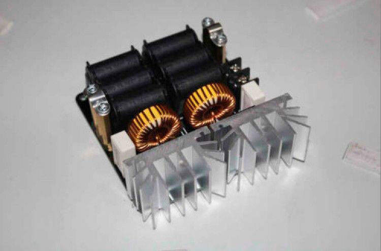
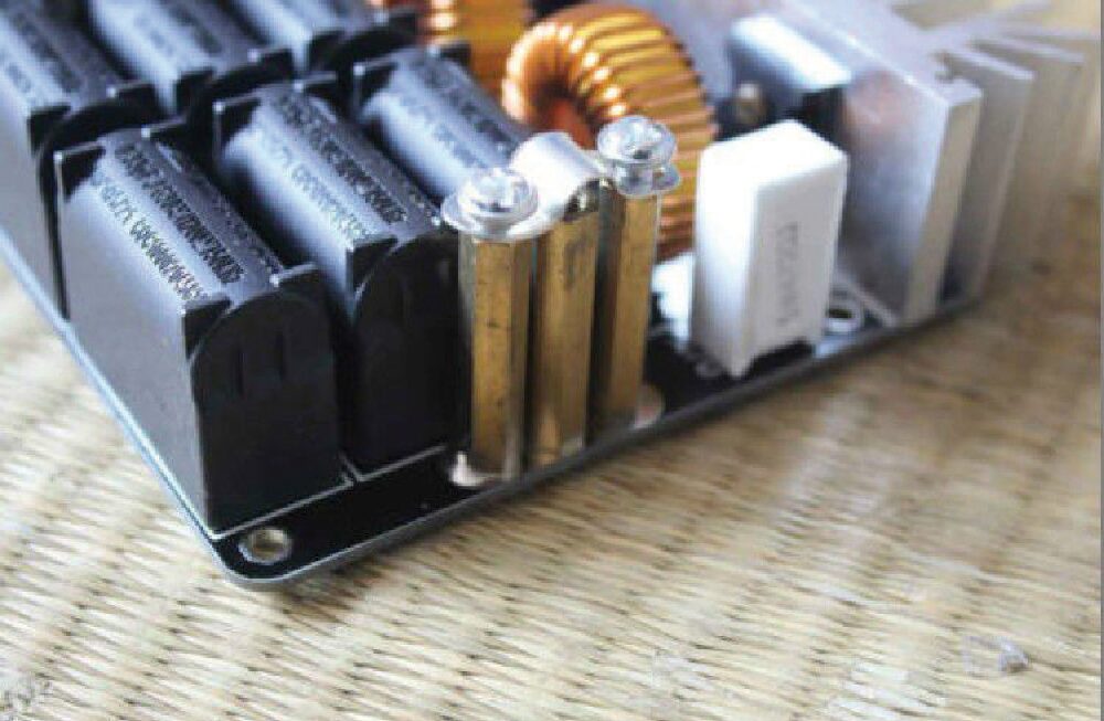
- Resonant Tank: A bank of six 0.33 μF MKP polypropylene capacitors provides a total capacitance of ~2 μF, chosen for their ability to handle high ripple currents without degradation.
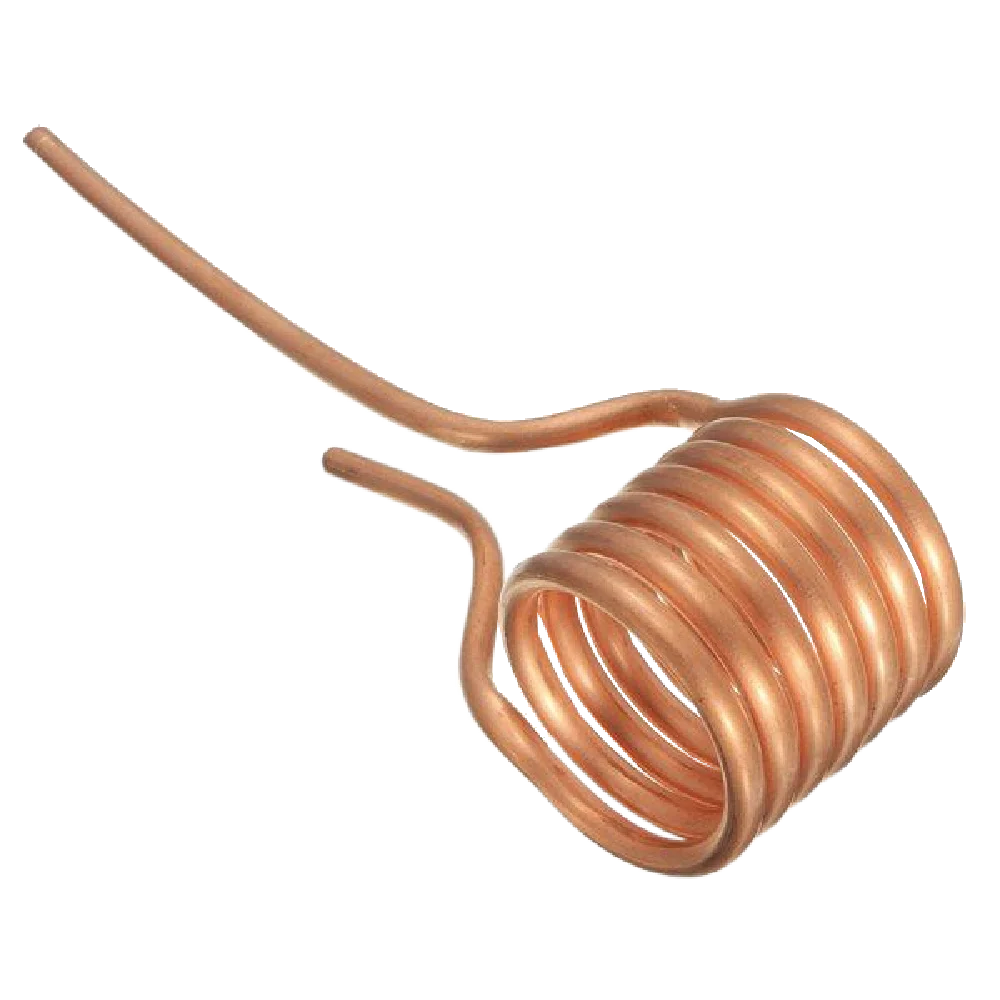
- Work Coil: Six turns of 6 mm hollow copper tubing, air-wound. The hollow design is a tactical choice: it manages high-frequency skin effect losses and can theoretically be cooled by circulating water if the duty cycle were to be significantly increased.
Key Performance Metrics
| Parameter | Value |
|---|---|
| Input Voltage | 48 VDC |
| Operating Frequency | ~100 kHz |
| Peak Magnetic Flux Density | 10.7 mT (107 Gauss) |
| Work Coil Current (RMS) | ~100 A |
| Power Consumption (Idle) | < 500 W |
| Power Consumption (Active) | 1,000 W – 1,500 W |
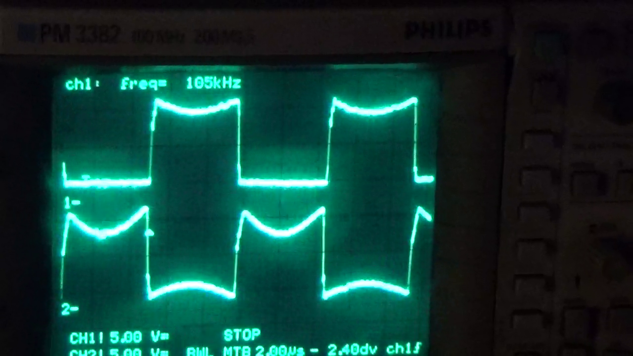
Note: Oscilloscope analysis confirms that the Gate-Source voltages of the MOSFETs remain perfectly in anti-phase, a vital safety requirement to prevent simultaneous conduction ("shoot-through"), which would result in immediate catastrophic failure.
Implications and Applications
While the most visceral demonstration of this project is the rapid heating and melting of a steel bolt, the underlying technology has profound implications for modern engineering.
Industrial Induction Heating
This project serves as a microcosm of the technology used in industrial metal hardening, annealing, and brazing. By controlling the frequency and the geometry of the work coil, manufacturers can selectively heat specific parts of a component without affecting the structural integrity of the rest of the piece.
Wireless Power Transfer
The ZVS circuit is a foundation for wireless energy transmission. By using coupled coils tuned to the same resonant frequency, electricity can be transferred across an air gap—a technology that is currently scaling from mobile phone chargers to electric vehicle charging pads.
Research and Tesla Coils
The ability to generate a high-power, high-frequency oscillating field is also a requirement for the ignition circuits of Tesla coils. Experimenters can use this ZVS driver as a reliable, high-efficiency power stage to explore the boundaries of high-voltage resonance.
Safety and Operational Protocols
Operating a 1,500W induction heater is not a trivial endeavor. The energy density involved requires a professional approach to safety.
- Thermal Hazards: The induction process is rapid. A metal object can transition from room temperature to a glowing orange-yellow incandescence in under ten seconds. The work coil itself, while air-cooled, will eventually become hot to the touch. Never handle components immediately after a cycle.
- Electromagnetic Interference (EMI): With 100A circulating in the work coil, the radiated field is significant. Do not operate this device near sensitive electronic equipment, medical devices (such as pacemakers), or magnetic storage media.
- Electrical Safety: The circuit is powered by 48 VDC at high current. While this is lower than mains voltage, the current capacity is enough to cause severe damage if a short circuit occurs. Always use an appropriately rated power supply (1,500W+) and ensure all connections are secured with proper terminal blocks.
- Component Maintenance: After prolonged use, the work coil may oxidize and darken. This is a normal byproduct of the heat and does not indicate failure, though users should ensure that the turns remain perfectly spaced to prevent short-circuiting.
Conclusion
The ZVS induction heater is more than a tool; it is a bridge between theoretical electromagnetism and tangible results. By applying the principles of ZVS to a resonant RLC circuit, we turn the invisible laws of physics into a visible demonstration of power. Whether utilized for metallurgical experimentation, wireless power research, or simply as an educational journey into power electronics, this 1,000W system provides a profound look at how modern technology bends the forces of nature to our will. Always approach this project with the respect that high-power electronics demand, and you will find it to be an endlessly rewarding engineering endeavor.