Mastering the Forge: Engineering a 1,000W ZVS Induction Heating System
The history of metalworking is a chronicle of human ingenuity, moving from open-pit fires to coal-fired bellows and, eventually, to the precision of electrical induction. Today, we stand at a technological frontier where we can manipulate the very fabric of electromagnetic fields to achieve what was once considered alchemy: melting metal through the invisible force of high-frequency oscillation. This article explores the construction and underlying physics of a 1,000W Zero Voltage Switching (ZVS) induction heater, a project that bridges the gap between theoretical electromagnetics and practical power electronics.
Main Facts: The Power of Invisible Fields
We live in an era saturated by electromagnetic waves. From the power distribution cables humming above our streets to the microwave ovens in our kitchens, we are surrounded by oscillating fields. However, the intensity of these fields is rarely harnessed for direct thermal conversion in a consumer setting—until now.
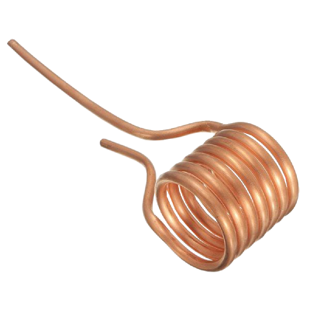
The project detailed here is a 1,000W ZVS-based induction heating system, capable of peaking at 1,500W. At its core, the device utilizes three fundamental physical principles: Magnetic Induction, Eddy Currents, and the Joule Effect. By passing a high-frequency alternating current through a copper coil (the "work coil"), we generate a rapidly changing magnetic field. When a conductive or ferromagnetic material is placed within this field, the changing magnetic flux induces a circular electrical current within the object—the "Eddy current." Due to the inherent resistance of the material, these currents generate heat with remarkable efficiency, a phenomenon known as the Joule effect.
Unlike a microwave oven, which operates at specific frequencies to excite water molecules, this induction system targets the metallic structure of the workpiece directly. The result is a rapid transition from room temperature to white-hot incandescence in mere seconds.
Chronology: From Concept to Incandescence
The development of this system followed a rigorous engineering path. Initially, the project sought to refine the efficiency of traditional induction heating by implementing the Royer oscillator topology.
- Phase One (Design & Simulation): The focus was on the RLC resonant circuit. By pairing a 1.26 µH work coil with a 2 µF capacitor bank, the team established a natural resonance frequency of approximately 100.3 kHz.
- Phase Two (Switching Strategy): To handle the high-power demand without destroying the semiconductor switches, the ZVS (Zero Voltage Switching) technique was employed. This ensures that the MOSFETs toggle when the voltage across their terminals is near zero, effectively eliminating power dissipation during the switching transition.
- Phase Three (Assembly & Calibration): The hardware was mounted to ensure thermal dissipation, with copper tubing forming the work coil to accommodate the massive 100A RMS currents circulating during operation.
- Phase Four (Testing): The final testing phase involved the controlled heating of steel samples, confirming that the circuit could achieve consistent, repeatable melting temperatures while maintaining a steady 17A draw from a 48V DC power source.
Supporting Data: The Physics of the Circuit
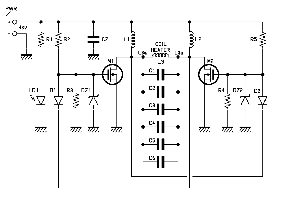
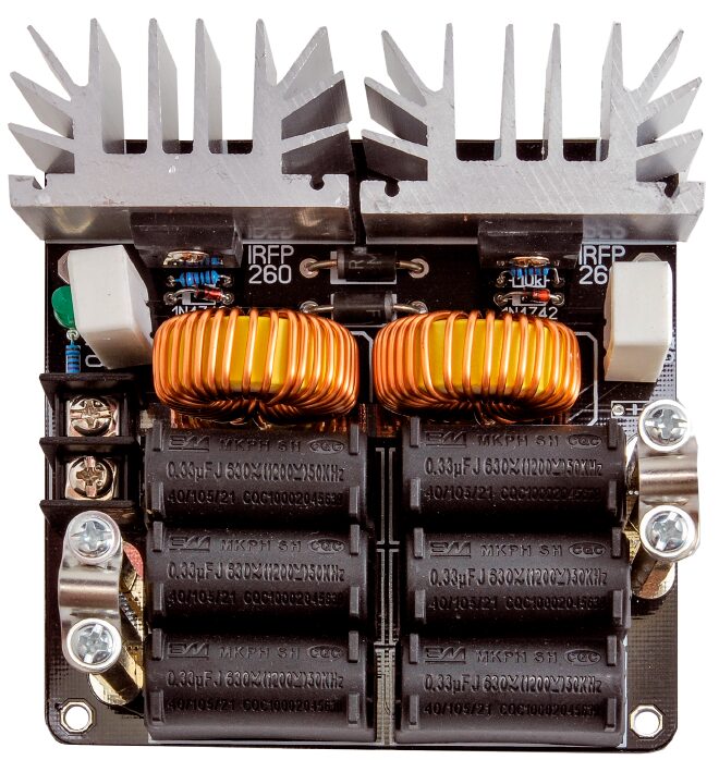
The heart of the system is the ZVS controller. The circuit acts as a self-oscillating resonant tank. When power is applied, one of the two Infineon IRFP260N MOSFETs enters a conduction state due to infinitesimal manufacturing variations. This pulls its drain to ground, forcing the opposite MOSFET into a cut-off state via a feedback diode (MUR420).
Key Performance Metrics:
- Operating Frequency: ~100 kHz.
- Input Voltage: 48 VDC (nominal).
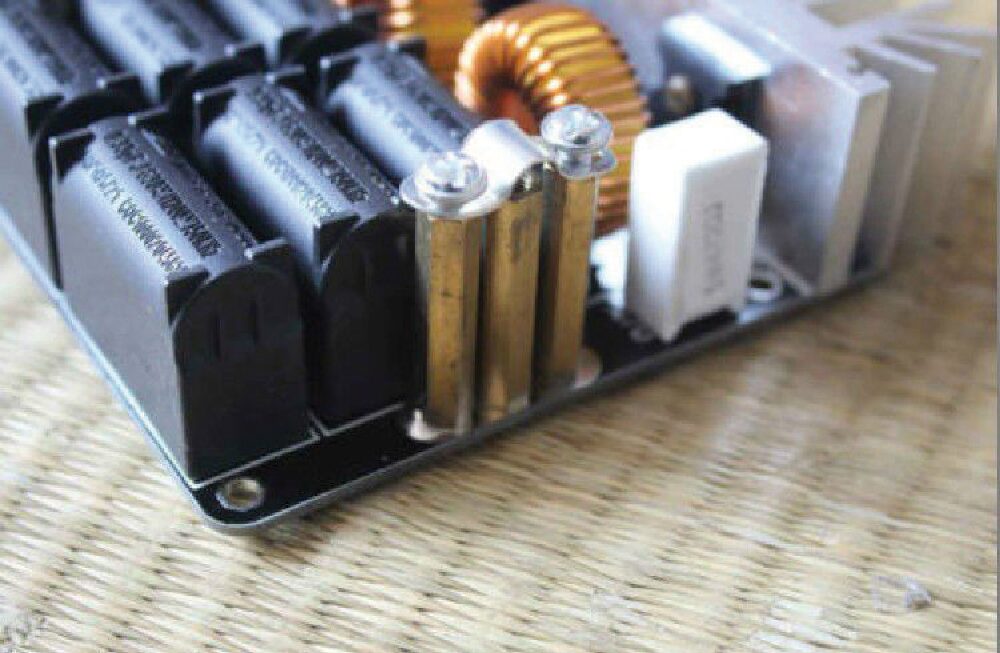
- Resonant Capacitance: 2 µF (constructed from six 0.33 µF MKP polypropylene capacitors).
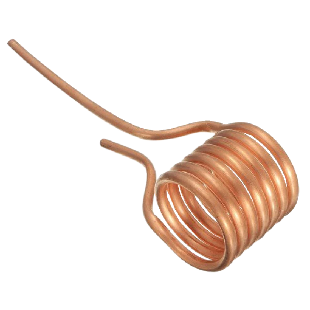
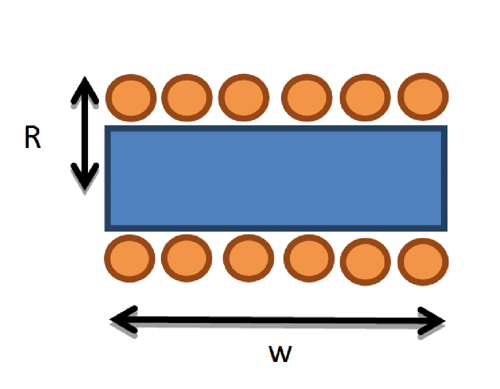
- Work Coil Geometry: 6 turns, 6 mm hollow copper tubing, 2.5 cm radius.
- Magnetic Flux Density: Approximately 10.7 mT (107 gauss) at the center of the coil.
The use of ZVS is critical here. In a standard switching circuit, the transition from "on" to "off" creates a period where voltage and current are both high, resulting in significant heat loss ($Pd = V times I$). By ensuring switching occurs at the zero-crossing of the voltage waveform, we preserve the longevity of the IRFP260N components, which are rated for 50A and possess an exceptionally low $R_DS(on)$ of 40 mΩ.
Official Technical Observations
During the testing phase, the research team utilized oscilloscope analysis to verify the health of the signal. The gate-source waveforms for the two MOSFETs demonstrate perfect anti-phase alignment. This is vital; any overlap in conduction would create a direct short-circuit across the power supply, leading to the catastrophic failure of the power stage.
The voltage waveform across the work coil shows a clean, near-perfect sine wave reaching 150V peak. This purity of signal confirms that the RLC tank is operating within its ideal parameters. Furthermore, the inclusion of 100 µH inductors (L1 and L2) successfully suppresses the high-frequency voltage spikes that typically plague high-power switching circuits.
Implications: The Future of Induction Technology
The implications of this project extend far beyond the ability to melt a bolt in a workshop. This ZVS architecture represents the backbone of modern, high-efficiency power transfer.
Industrial and Practical Applications:
- Wireless Power Transfer: The same principles used to heat metal can be tuned for resonant inductive coupling, enabling the wireless charging of everything from mobile devices to electric vehicles.
- Material Science: Induction heating is a clean, localized method for heat-treating, annealing, and forging, offering a significant reduction in the environmental footprint compared to traditional gas furnaces.
- Education and R&D: By modularizing the ZVS circuit, researchers can investigate the skin effect, magnetic permeability, and the behavior of ferromagnetic materials under high-frequency stress.
Safety and Practical Guidance
While the project is a testament to electronic efficiency, it is not without inherent risks. The magnetic fields generated are powerful enough to interfere with sensitive electronics and medical devices. Users must maintain a significant distance from the coil during operation to avoid the induction of currents in metallic jewelry or nearby instruments.
The rapid generation of heat is the system’s primary function, but it is also its primary danger. The work coil itself, while air-cooled, will eventually darken and reach extreme temperatures. The workpiece, once removed from the field, remains a severe burn hazard for an extended duration.
Assembly Best Practices:
- Terminal Integrity: Ensure all high-current connections are tightened to prevent arcing.
- Component Selection: Only use MKP (polypropylene) capacitors. Standard ceramic or electrolytic capacitors will fail catastrophically under the high-frequency, high-current ripple of a 1,000W tank circuit.
- Cooling: While the ZVS circuit is efficient, the sheer power level necessitates robust airflow over the MOSFET heatsinks.
Conclusion
The 1,000W ZVS induction heater is more than a tool; it is a profound demonstration of the control we have over the physical world. By modulating the oscillation of electrons, we can command the thermal state of matter. Whether for the hobbyist looking to explore the fringes of power electronics or the engineer designing the next generation of inductive charging systems, this circuit serves as a foundational blueprint. It reminds us that with a firm grasp of Faraday’s Law and the elegance of Zero Voltage Switching, we can truly harness the power of the invisible.