Mastering Analogue Inputs on the Raspberry Pi: From Precision LED Control to a DIY Internet Radio
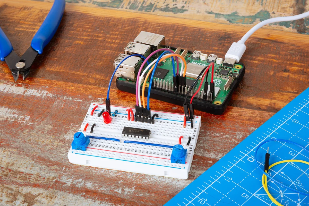
Main Facts: Bridging the Digital and Analogue Worlds
For all their modern computational power, single-board computers like the Raspberry Pi speak a fundamentally digital language. Operating on discrete high and low voltage states, they are naturally adept at managing digital sensors, push buttons, and standard logic outputs. However, the physical world is stubbornly analogue. Temperature, light, distance, and user input via rotary dials exist on smooth, continuous sliding scales.
Historically, coaxing an analogue reading out of a Raspberry Pi required clever workarounds, such as timing capacitor discharge rates. While functional, these methods are notoriously jittery, imprecise, and unreliable for complex projects.
Enter the analogue-to-digital converter (ADC)—specifically the MCP3008 chip. Featured prominently in the newly updated Raspberry Pi Press guide, Simple electronics with GPIO Zero (2nd Edition), this 10-bit ADC provides eight discrete input channels that seamlessly translate continuous voltage fluctuations into crisp, precise digital data.
In a comprehensive tutorial drawn from Raspberry Pi Official Magazine #167 and the new book, makers are taught how to integrate the MCP3008 using Python and the beginner-friendly gpiozero library. Moving past basic LED brightness control, the project scales up into a fully functioning, physical dual-potentiometer internet radio. This article explores the mechanics, step-by-step chronology, underlying data protocols, and broader implications of bringing hardware-level analogue control to the Raspberry Pi ecosystem.
Chronology: A Step-by-Step Guide to Building the Circuit
Developing an analogue-driven project on a Raspberry Pi requires a methodical approach, beginning with hardware preparation and ending with advanced software orchestration.
Step 1: Enabling SPI Communication
Before wiring any physical components, the Raspberry Pi must be configured to communicate with the MCP3008 chip using the Serial Peripheral Interface (SPI) protocol.
- Install the SPI Python Library: Open a terminal window and enter the following command to ensure the
spidevpackage is present:sudo apt install python3-spidev - Enable the Interface: Navigate to the Raspberry Pi desktop configuration menu via Preferences > Control Centre > Interfaces, locate SPI, and toggle it to "Enabled." Alternatively, use the command-line utility by running
sudo raspi-config, navigating to Interface Options, enabling SPI, and rebooting the device.
Step 2: Wiring the ADC and Potentiometers
Safety first: Always power down the Raspberry Pi before altering or assembling physical circuitry on a breadboard.
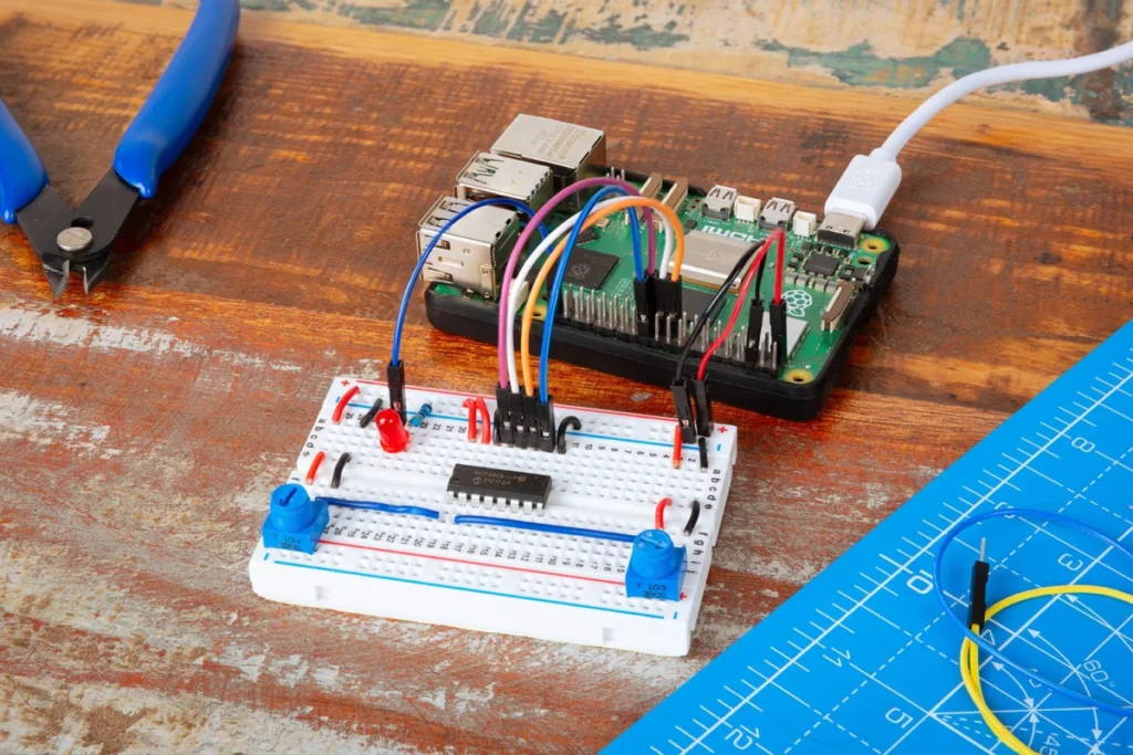
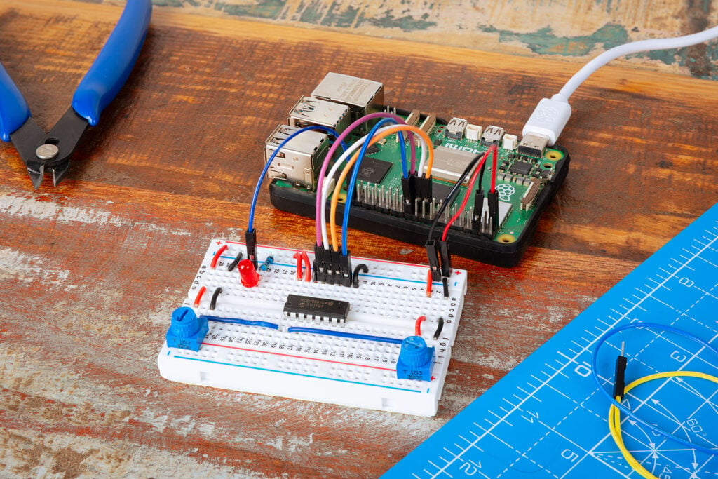
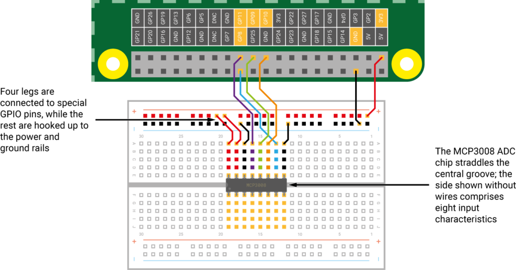
- Position the MCP3008: Place the ADC chip squarely across the central dividing trough of a standard breadboard.
- Power and Ground Connections: Run jumper wires from the chip’s power pins to the positive rail (supplied by the Pi’s 3.3V pin) and ground pins to the negative rail (connected to GND).
- SPI Data Pins: Connect the middle legs of the ADC to the Raspberry Pi’s hardware SPI pins: GPIO 8 (CE0), GPIO 10 (MOSI), GPIO 9 (MISO), and GPIO 11 (SCLK).
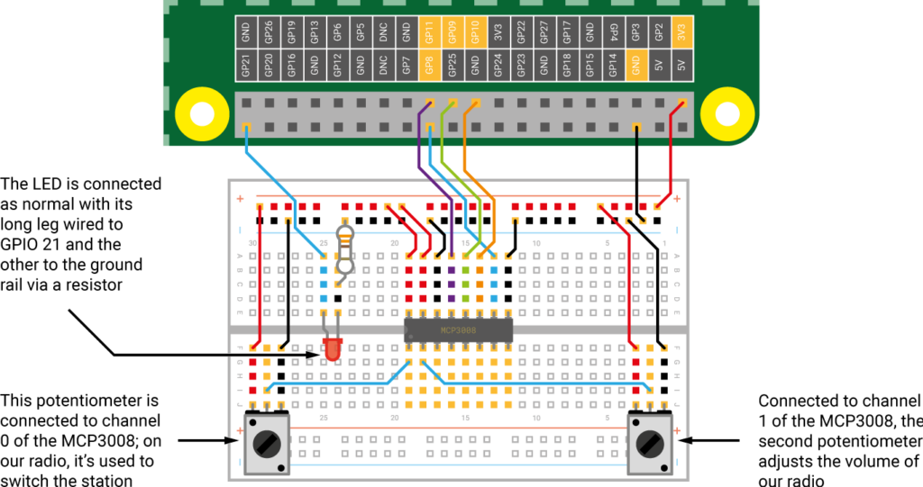
- Attaching the Potentiometers: Insert the first variable resistor (potentiometer). Connect its outer legs to the 3.3V power rail and ground rail respectively, and hook its middle wiper leg directly into Channel 0 (
CH0) of the MCP3008. Add a second potentiometer later, wiring its wiper to Channel 1 (CH1).
Step 3: Reading Analogue Values in Python
To verify the setup, write a minimal Python script to stream the continuous voltage values captured by the potentiometer:
from gpiozero import MCP3008

pot = MCP3008(channel=0)

while True:
    print(pot.value)
Running this script (test_pot.py) and rotating the physical dial will output a continuous stream of floats ranging between 0.0 and 1.0 in the terminal window.
Step 4: Controlling an LED via Pulse-Width Modulation (PWM)
By pairing the analogue sensor data directly with a Pulse-Width Modulation LED (PWMLED), makers can dynamically control lighting intensity. Connect the positive leg of an LED to GPIO 21, and the shorter negative leg through a current-limiting resistor to ground.
Using gpiozero’s native source-and-values architecture, the code is remarkably concise:
from gpiozero import MCP3008, PWMLED
from signal import pause

pot = MCP3008(0)
led = PWMLED(21)

led.source = pot.values
pause()
Step 5: Scaling Up to a Physical Internet Radio
To transform the dual-potentiometer hardware stack into a functional internet radio, install the VLC media player backend to handle streaming audio streams:
sudo apt install vlcUsing a Python script that integrates Popen, run, and WirePlumber/PipeWire audio control utilities (wpctl), one potentiometer is mapped to switch seamlessly between internet audio streams (such as SomaFM Groove Salad and Indie Pop), while the second potentiometer adjusts system playback volume in real-time.
Supporting Data & Technical Specifications
Understanding the hardware specifications highlights why an external ADC like the MCP3008 is superior to rudimentary software-timed hacks:
- Resolution: The MCP3008 is a 10-bit Analogue-to-Digital Converter. This means it divides a 0V to 3.3V input range into $2^10$ (or 1,024) discrete digital steps, offering fine-grained sensitivity for smooth control loops.
- Input Channels: It features 8 single-ended input channels (Channels 0 through 7), allowing multiple analogue sensors—such as photoresistors, temperature sensors, joysticks, and linear potentiometers—to share a single SPI bus.
- Communication Protocol: Utilizing SPI (Serial Peripheral Interface), data transfer speeds are exceptionally fast, preventing the latency bottlenecks associated with bit-banging or software-emulated analogue reads.
- Library Framework: The
gpiozeroPython library abstracts away the complex underlying bit-shifting mathematics, letting developers treat analogue inputs with the same high-level intuition applied to simple digital buttons and LEDs.
Official Responses and Educational Insights
The release of Simple electronics with GPIO Zero (2nd Edition) marks a significant milestone for Raspberry Pi Press, reflecting years of community feedback regarding hardware education.
According to the editorial team at Raspberry Pi, the primary goal of the updated text is to lower the barrier to entry for physical computing without sacrificing technical depth. "While digital inputs and outputs teach foundational coding principles, physical computing truly comes alive when you introduce variable, real-world inputs," notes the editorial board. "By leveraging the MCP3008 alongside the streamlined gpiozero library, students and hobbyists can bypass frustrating low-level register configurations and jump straight into creative prototyping."
Educators have similarly praised the source-and-values paradigm embedded within gpiozero. By allowing physical properties—like the rotation angle of a knob—to be directly piped into output components like PWM LEDs or audio streams without verbose polling loops, young learners grasp object-oriented data streams and reactive programming paradigms far more organically.
Implications for Makers, Educators, and IoT Engineers
The integration of robust analogue-to-digital conversion into the standard Raspberry Pi curriculum carries far-reaching implications across multiple domains:
1. Enhanced Prototyping Capabilities for IoT
Internet of Things (IoT) devices frequently rely on environmental monitoring—gauging soil moisture, ambient light levels, or liquid flows. These are inherently analogue metrics. By standardizing the MCP3008 and SPI communication paths, engineers can rapidly prototype industrial monitoring nodes or smart-home controllers using readily available components, bridging the gap between low-cost single-board computers and industrial-grade sensor arrays.
2. Pedagogy and Hands-On STEM Education
For classrooms, the transition from binary inputs (on/off switches) to continuous variables (sliders and dials) opens up entirely new categories of student projects. As demonstrated by the internet radio project, students are no longer restricted to blinking lights; they can build tangible, interactive appliances that mirror consumer electronics they use every day.
3. The Re-Enchantment of Physical Computing
In an era dominated by touchscreens and abstract software interfaces, physical computing projects grounded in tactile hardware restore a sense of craftsmanship to software engineering. Twisting a heavy rotary dial to adjust audio volume or dim an indicator light injects a visceral, human-centric element back into digital creation.
For those eager to expand their hardware repertoire beyond basic blinking LEDs, guides like Simple electronics with GPIO Zero (2nd Edition) provide an invaluable roadmap. Whether building a motion-sensing alarm, a laser tripwire, or a custom-tailored internet radio, the horizon of Raspberry Pi projects has never looked broader—or more analogue.