The Polarity Paradox: A Masterclass in Navigating Magnetic Field Identification
In the world of precision engineering, hobbyist fabrication, and industrial assembly, few components are as deceptively simple—yet infuriatingly complex—as the permanent magnet. For makers who have spent hours gluing magnetic closures into 3D-printed enclosures or seating neodymium magnets into intricate gear assemblies, the "snap" of a magnet adhering to the wrong side of a housing is a familiar, frustrating sound.
The struggle to distinguish between a magnetic north and south pole is not merely a matter of trial and error; it is a fundamental challenge of physics that can derail even the most well-intentioned projects. Recently, the technical creator [Clough42] released an exhaustive guide demystifying the identification of magnetic poles, providing a comprehensive toolkit for ensuring that "wrong-way" assembly becomes a thing of the past.
The Core Problem: Why Polarity Matters
Whether you are designing a high-end kinetic sculpture, a magnetically coupled sensor array, or a simple cupboard catch, consistency is the bedrock of quality. When magnetic polarity is inconsistent, the intended attraction becomes repulsion, rendering a design functional only in theory.
The primary challenge is that magnets—unlike batteries or electrical components—possess no visual indicators of their internal state. To the human eye, a nickel-plated neodymium cube looks identical whether its north pole faces left or right. This ambiguity is the source of countless production errors. If a maker inadvertently mixes orientations in a multi-magnet array, the resulting field flux can cause unexpected mechanical resistance or, worse, prevent a device from engaging entirely.
Chronology of Magnetic Identification Techniques
[Clough42] outlines a clear progression of methods for identifying poles, ranging from rudimentary physical interactions to sophisticated digital sensing.
1. The Reference Magnet Method (The Baseline)
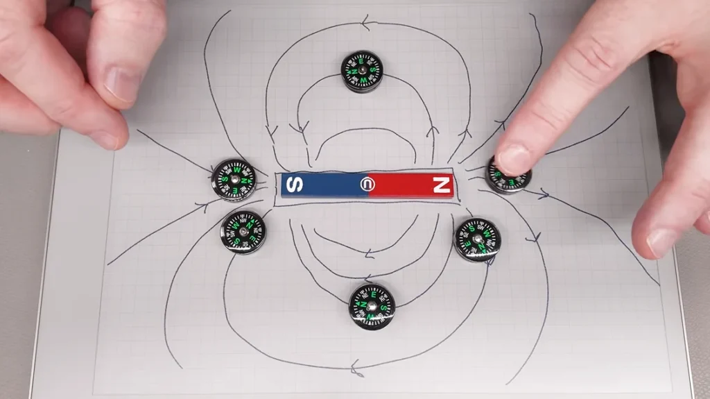
The most ancient and reliable technique is the use of a known-good reference magnet. By labeling a single, trusted magnet with a permanent marker, the user creates a physical standard. Through the fundamental law of magnetism—that like poles repel and opposites attract—any unknown magnet can be identified by its reaction to the reference. While simple, this method requires the user to maintain a dedicated "master" magnet, which itself can become a source of error if mislabeled.
2. The Compass Integration
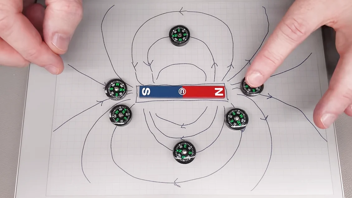
For those who lack a reference magnet, a standard magnetic compass remains a stalwart tool. A compass needle is, in itself, a floating permanent magnet. Because the "north" arrow of a compass is designed to point toward the Earth’s magnetic north, it is actually a magnetic south pole (as it is attracted to the Earth’s geographic north). By observing which end of the compass needle is drawn to the unknown magnet, one can derive the polarity through simple deduction.
3. Electronic Sensing: Hall Effect and Beyond
As projects scale in complexity, manual verification becomes inefficient. Enter the Hall effect sensor. These devices translate magnetic flux density into an electrical signal. However, as [Clough42] demonstrates, these sensors are not always the "silver bullet" they appear to be.
Supporting Data: The Nuances of Magnetic Sensing
A critical segment of [Clough42]’s analysis focuses on the deceptive nature of electronic sensors. In a practical demonstration, he utilizes a Hall effect sensor board designed to illuminate an LED when the south pole of a magnet is brought into proximity.
The Sensor Orientation Trap
The experiment revealed that the sensor could be triggered by the north pole if the magnet was placed behind the sensor board. This highlights a crucial technical distinction: Hall effect sensors do not "see" poles; they measure magnetic field vector orientation.
If a sensor is sensitive to the flux lines entering its face, it will treat a north pole approaching from the rear identically to a south pole approaching from the front, provided the magnetic flux lines are traversing the sensor element in the same direction. This realization is vital for engineers. Relying on an electronic sensor without understanding its specific data sheet—specifically whether it is a "latching," "unipolar," or "bipolar" sensor—can lead to systematic errors in automated assembly lines.
Digital Compass Interference
The video further explores the limitations of modern smartphone magnetometers. By using an app that visualizes internal phone sensors, [Clough42] demonstrates how moving a strong magnet near the device can cause the digital compass to report wild fluctuations. Because mobile devices are packed with complex circuitry, they are highly susceptible to electromagnetic interference. Relying on a phone app to orient magnets is, at best, a rough estimation and, at worst, a source of total inaccuracy due to field distortion.
Implications for the Maker Community
The broader implication of this study is a call for "metrological literacy" among makers. It is not enough to own a tool; one must understand the physics governing the tool’s interaction with the physical world.
Standardizing Calibration
For professional and hobbyist shops, the recommendation is clear: establish a formal protocol for magnet handling. This includes:
- Physical Labeling: Every shop should have a dedicated reference magnet stored in a neutral area away from other ferrous materials.
- Documentation: Maintain a log of magnetic component specifications, including the specific type of sensor used for verification.
- Verification Cycles: Periodically recalibrate electronic sensors using the reference magnet to ensure that environmental factors—such as temperature shifts or nearby high-current cabling—haven’t skewed the sensor’s sensitivity threshold.
Design Considerations
When designing products that rely on magnetic closures, engineers should consider incorporating physical keys (like asymmetrical housing shapes) that prevent magnets from being installed in the wrong orientation. If the geometry is physically constrained, the reliance on human error during assembly is significantly reduced.
The Future of Magnetic Assembly
As we move toward more integrated electronics, the ability to accurately manipulate and identify magnetic poles will only grow in importance. From the tiny magnets in haptic feedback engines of smartphones to the massive permanent magnets in high-efficiency electric vehicle motors, the principles of polarity remain constant.
[Clough42]’s contribution to this field serves as a sobering reminder: technology often abstracts the physical reality of our work, but it never replaces the need for fundamental understanding. The next time you find yourself fumbling with a pair of magnets, remember that you are dealing with the invisible, yet highly predictable, laws of electromagnetism. By respecting the physics of the field, rather than just the output of a sensor, we can ensure our designs work exactly as intended—every single time.
For those interested in the deep-dive theory, investigating the history of magnetic flux and the work of scientists like Gauss and Tesla provides the necessary context to appreciate why these small, silver disks are among the most fascinating components in a maker’s inventory. Whether you are using a simple compass or an advanced Hall effect array, the rule remains: measure twice, label once, and never trust a sensor until you have verified its frame of reference.
For more information on magnetic theory and to watch the full demonstration by [Clough42], visit his official YouTube channel.