The Art of Automation: How One Maker Solved the Tedium of Flip-Dot Production
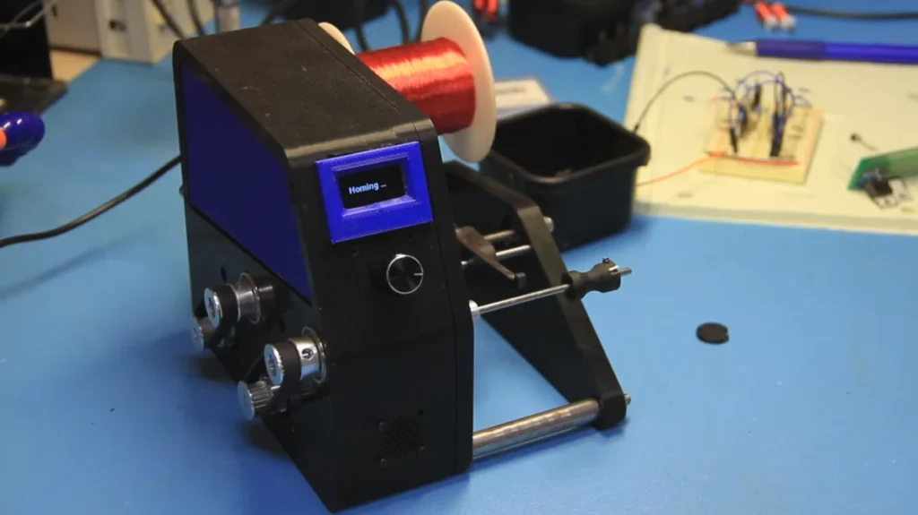
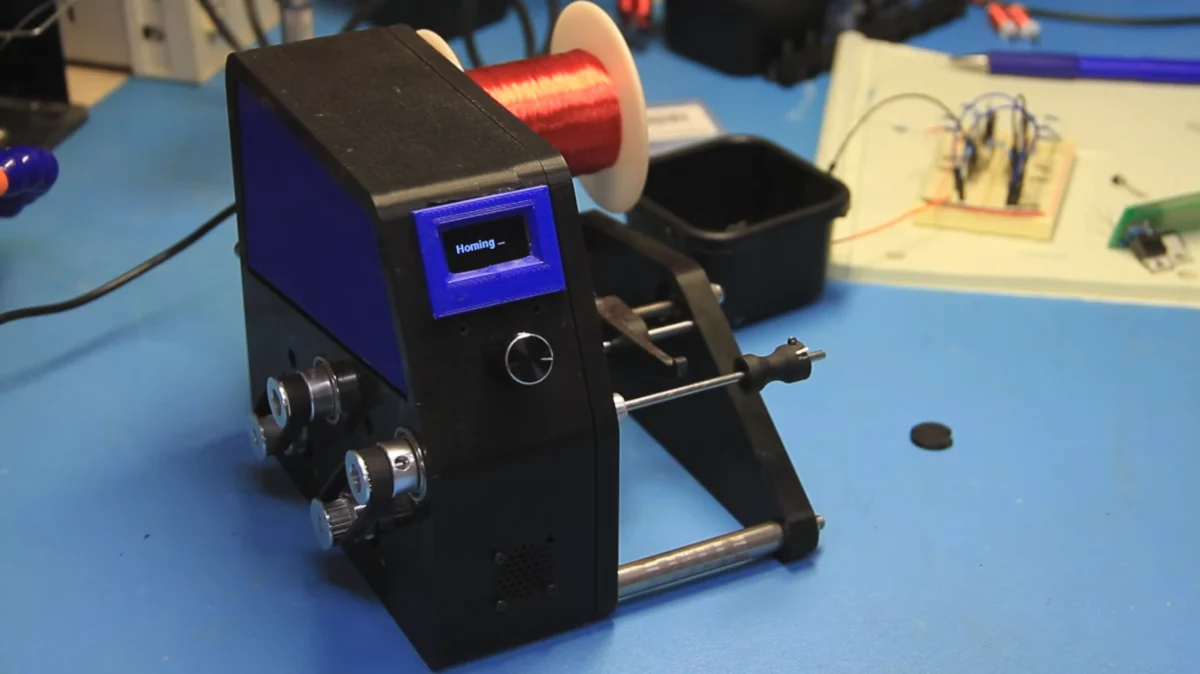
For the uninitiated, the flip-dot display—those nostalgic, clacking boards found in old train stations and airports—represents a masterpiece of electromechanical engineering. However, for [Larry], the maker behind a recent innovative project, the charm of these displays was quickly overshadowed by the grueling reality of their construction. Specifically, the necessity of winding hundreds, if not thousands, of electromagnetic coils for a custom flip-dot matrix proved to be a bottleneck that threatened to stall his entire project.
Rather than succumb to the repetitive strain of manual labor, [Larry] turned his attention toward automation. The result is a bespoke, 3D-printed coil-winding machine that not only solves his immediate production problem but serves as a masterclass in desktop manufacturing and precision control.
The Core Challenge: Why Manual Winding Fails
To understand the necessity of this project, one must first understand the requirements of a flip-dot pixel. Each "dot" in a matrix requires a pair of electromagnetic coils to generate the magnetic fields necessary to flip a permanent magnet back and forth. When building a display of any reasonable resolution, the number of coils required balloons rapidly.
Manual winding is not merely tedious; it is prone to human error. Consistent tension, precise layer counts, and even wire distribution are essential for ensuring that every coil has the same electrical resistance and magnetic force. If one coil is wound loosely while another is tight, the display will suffer from inconsistent performance, resulting in "lazy" dots that fail to flip or stick in intermediate positions. By designing an automated winder, [Larry] moved from the unpredictable nature of hand-winding to a system capable of industrial-grade repeatability.
Chronology of Development: From Concept to Coil
The development of the coil winder followed a rigorous engineering path, moving from conceptual requirements to final assembly.
Phase 1: Conceptualization and Kinematics
The project began with the definition of the mechanical requirements. The machine needed to perform two simultaneous, synchronized movements: the rotation of the bobbin to accept the wire and the lateral movement of a guide carriage to ensure that the wire was laid down in perfectly adjacent turns. [Larry] determined that stepper motors were the only viable solution to provide the high-torque, incremental control required for these tasks.
Phase 2: Structural Integration
The structural backbone of the machine is a hybrid of 3D-printed components and off-the-shelf hardware. Using PLA for the primary housing kept the weight down while allowing for rapid iteration of parts. Metal rods were integrated to provide structural rigidity, ensuring that the guide carriage would not flex under the tension of the wire. Bearings were sourced for both the wire spool holder and the bobbin shaft, minimizing friction and ensuring smooth, silent operation.
Phase 3: Electronics and Logic
The control system is anchored by a Teensy microcontroller. The choice of a Teensy—known for its speed and I/O capabilities—allowed [Larry] to implement a user-friendly interface. An OLED display provides real-time feedback on the winding process, while a rotary encoder serves as the primary input for settings, such as total turns and winding speed. The software includes a robust homing sequence; before any wire is placed, the machine calibrates the guide carriage against an end-stop switch, ensuring that every batch starts from a known, absolute zero position.
Supporting Data: The Anatomy of the Machine
The machine’s performance is defined by its mechanical efficiency and control parameters. Below is a breakdown of the technical specifications that allow for its high-precision operation:
- Motion Control: Dual-stepper architecture. The primary motor handles bobbin rotation, while the secondary motor drives a lead-screw-style carriage to distribute wire evenly.
- Tensioning System: A passive friction-based tensioner consisting of two foam pads. This allows for adjustable pressure, ensuring the wire remains taut enough to prevent tangles without being so tight that it snaps or stresses the bobbin structure.
- User Interface: A Teensy-based controller paired with a crisp OLED display, allowing the operator to track the number of layers applied and the current turn count.
- Structural Materials: 3D-printed PLA housing, reinforced with stainless steel rods and high-grade ball bearings to maintain alignment over extended production cycles.
The efficiency of this system is not just in the speed of the winding, but in the uniformity of the output. By automating the "layer counting" process, [Larry] ensures that every coil produced by the machine is identical in inductance and resistance, a critical factor for the longevity of a large-scale flip-dot matrix.
Official Perspective and Design Philosophy
While [Larry] has not released a formal "manifesto" regarding his design, the project’s documentation suggests a philosophy centered on "maker-driven production." In the open-source community, there is a recurring theme that modern fabrication tools (like 3D printers and microcontrollers) should not just be used to create trinkets, but to create the means of production for more complex devices.
By open-sourcing the logic and the structural design of his winder, [Larry] is contributing to a broader movement within the DIY electronics space. Similar projects have emerged recently, such as the adaptation of Ender-3 3D printers for stator winding. However, [Larry]’s machine is notable for its specific optimization: it is not a repurposed 3D printer, but a machine built from the ground up for a singular, narrow task. This "specialist" approach often yields higher reliability than "generalist" machines that attempt to perform too many functions.
Implications: The Future of Home-Brewed Electromechanical Displays
The existence of such a machine has significant implications for the hobbyist community. Historically, projects like large-scale flip-dot displays were the exclusive domain of those with access to industrial manufacturing or the patience of a saint. By lowering the barrier to entry, [Larry] is effectively democratizing the production of high-end display hardware.
Scalability of DIY Projects
If the process of creating complex components (like thousands of electromagnetic coils) can be automated with a $100 machine, the scope of what a single maker can achieve expands exponentially. We may soon see hobbyist-built displays that rival commercial offerings in terms of resolution and reliability.
The Cycle of Maker Innovation
This project highlights a virtuous cycle in the maker community. One person builds a tool to solve a problem (the coil winder), which then enables the completion of a larger, more ambitious project (the flip-dot display). Others then take that tool, refine it, and apply it to entirely different fields—such as building small brushless DC motors or custom inductors for high-frequency radio applications.
Moving Toward "Desktop Factory" Standards
As we look at the evolution of this winder, it is clear that the line between "prototyping" and "manufacturing" is blurring. When a machine can reliably churn out precision-wound components in a living room, the need for outsourcing to overseas factories for small-batch electronic parts diminishes. This shifts the power back to the individual designer, allowing for rapid iteration and custom-tailored solutions that would be cost-prohibitive in a commercial manufacturing environment.
Conclusion
The story of [Larry]’s coil-winding machine is a testament to the ingenuity of the modern maker. By identifying a major bottleneck in his workflow and constructing a targeted solution, he has not only eased his own labor but provided a blueprint for others to follow. Whether you are interested in building your own retro-style display or simply admire the elegance of a well-engineered automation tool, this project serves as a compelling reminder: if the tools you need don’t exist, you can build them.
For those interested in the application of this machine, [Larry]’s ongoing work on his custom flip-dot design remains a project to watch. As the matrix continues to grow, so too will the utility of his automated winder, likely setting a new standard for how we approach complex, component-heavy builds in the future. As the clacking of the flip-dots begins, it will be the silent, steady hum of the winder that made the symphony of motion possible.