Mastering Ambient Light Sensing: A Comprehensive Guide to the BH1750 Sensor and GY-302 Module with Arduino
In the realm of microcontroller-based prototyping, environmental monitoring has evolved from simple analog readings to precise, digital data acquisition. Among the most popular components for measuring ambient light is the BH1750 digital ambient light sensor, typically packaged on the ubiquitous GY-302 breakout board. Recently put through its paces by electronics blogger AdriRobot using an Arduino UNO, this compact module continues to prove its worth for makers, engineers, and hobbyists alike.
This comprehensive technical guide explores the BH1750 architecture, its operational modes, hardware specifications, and a step-by-step implementation featuring an Arduino UNO and an I2C OLED display.
Main Facts: What is the BH1750 and GY-302?
At its core, the BH1750 is a digital ambient light sensor IC manufactured by ROHM Semiconductor. Unlike basic Photoresistors (LDRs) that merely change resistance based on light exposure—requiring complex calibration and analog-to-digital conversion formulas—the BH1750 integrates a 16-bit analog-to-digital converter (ADC) directly onto the silicon.
Key Technical Highlights:
- Direct Digital Output: Communicates via the standard Inter-Integrated Circuit (I2C) bus, eliminating the need for analog input pins.
- Wide Measurement Range: Capable of detecting light levels from 1 lux up to 65,535 lux.
- Human Eye Response: Approximates the photopic response of the human visual system.
- Ready-to-Use Breakout: The GY-302 module simplifies integration by adding necessary support components, such as a voltage regulator and pull-up resistors, making it immediately compatible with Arduino, ESP32, Raspberry Pi, and other microcontrollers.
Chronology of Development and Testing
The integration of digital I2C light sensors in the maker community has progressed significantly over the last decade. Early prototyping relied heavily on Cadmium Sulfide (CdS) photoresistors paired with a fixed resistor to create a simple voltage divider. While cheap, these setups were notoriously inaccurate, drifted with temperature, and lacked standardized units of measurement.
The introduction of dedicated digital ICs like the BH1750 revolutionized low-cost environmental sensing. By moving the lux calculation directly to the sensor’s internal logic, developers could obtain consistent, repeatable measurements across different hardware platforms.
In the recent project documented by AdriRobot, the evaluation followed a structured engineering timeline:
- Initial Bench Testing: Verifying I2C communication using the Arduino IDE’s
i2c_scannerutility to confirm address recognition at0x23. - Library Integration: Implementing Christopher Laws’ BH1750 Arduino library to manage operational modes and raw-to-lux data conversion.
- Serial Monitoring Phase: Logging real-time lux values to the serial console at one-second intervals.
- Display Integration: Upgrading the standalone setup by attaching a 0.96-inch SSD1306 OLED display to create a fully self-contained digital lux meter.
- Advanced Deployment: Expanding the sensor’s use case into multi-sensor environmental nodes, such as ESP32-based weather stations paired with DHT22 temperature/humidity and BMP280 barometric sensors.
Supporting Data and Technical Specifications
Understanding the mathematical and operational parameters of the BH1750 is crucial for fine-tuning projects that require high accuracy or specific response times.

Understanding the Lux
The lux (lx) is the SI unit of illuminance, defined as one lumen per square metre ($textlm/m^2$). It measures luminous flux per unit area, weighted according to the luminosity function—a standardized model of human visual sensitivity to light brightness.
- Full Moon Night: $approx 1text lx$
- Brightly Lit Office: $approx 400text lx$
- Direct Sunlight: $32,000text to 100,000text lx$
Measurement Modes and Resolutions
The BH1750 operates across six distinct modes, categorized into Continuous Measurement and Single Measurement groups:
- Continuous Measurement Mode: The sensor continuously measures light intensity without user intervention after initialization.
- Single Measurement Mode: The sensor takes a single reading, transmits it, and automatically powers down into a low-power standby state, conserving energy in battery-powered applications.
Each mode offers varying degrees of precision and maximum measurable range:
| Mode | Resolution / Precision | Maximum Range | Behavior |
|---|---|---|---|
| High Resolution Mode | 1 lux | 54,612.5 lx | Default mode selected by standard libraries. |
| High Resolution Mode 2 | 0.5 lux | 27,306.25 lx | Higher precision, lower maximum ceiling. |
| Low Resolution Mode | 4 lux | 54,612.5 lx | Faster conversion time (typically 16ms). |
Internally, the sensor outputs a 16-bit integer. The software library translates this raw value into standard lux units by dividing the integer by a calibration factor of 1.2. Error handling is built into standard implementations: a returned value of -1 indicates missing or invalid data, while -2 signals an unconfigured device.
Furthermore, advanced users can adjust the measurement sensitivity time window by modifying the MTreg (Measurement Time register). Ranging from 32 to 254 (with a default value of 69), adjusting MTreg allows developers to optimize the sensor for exceptionally dark or intensely bright environments.
The GY-302 Module Breakdown
The GY-302 breakout board is engineered for plug-and-play compatibility with both 3.3V and 5V microcontrollers:
- Voltage Regulation: Features an onboard 3.3V Low Dropout (LDO) linear voltage regulator (commonly marked
662K) accompanied by filtering capacitors. This allows the module to be powered directly from an Arduino’s 5VVCCpin, safely supplying up to 250 mA with an input tolerance of up to 6.5V. - Bus Conditioning: Integrates dual $4.7text kOmega$ pull-up resistors on the Serial Clock Line (SCL) and Serial Data Line (SDA) to ensure stable I2C signal integrity.
- Pinout Architecture:
VCC: Power supply input (3.3V to 5V)GND: Common groundSCL: I2C ClockSDA: I2C DataADDR: I2C Address Selection pin
Managing I2C Addresses
To prevent address collisions when deploying multiple I2C devices, the BH1750 provides the ADDR pin.

- When
ADDRis pulled LOW (connected to GND), the I2C address is0x23. - When
ADDRis pulled HIGH (connected to VCC), the I2C address shifts to0x5C.
On the standard GY-302 module, the ADDR pin is tied to ground via an onboard $4.7text kOmega$ pull-down resistor by default, meaning the device responds out-of-the-box at address 0x23.
Implementation Guide: Arduino UNO and OLED Display
Building a standalone digital lux meter is an excellent beginner-to-intermediate project that demonstrates the power of the I2C communication protocol. Because both the BH1750 sensor and typical OLED displays operate on the I2C bus, they can share the exact same clock and data lines simultaneously, requiring only unique hardware addresses to function without conflict.
Required Components
- Arduino UNO (or compatible microcontrollers like ESP32, Arduino Nano, Mega)
- GY-302 Breakout Board featuring the BH1750 sensor
- 0.96-inch OLED Display (128×64 pixels, SSD1306 driver, I2C interface)
- Male-to-Female and Male-to-Male Jumper Wires
- Breadboard (optional, for neat wiring)
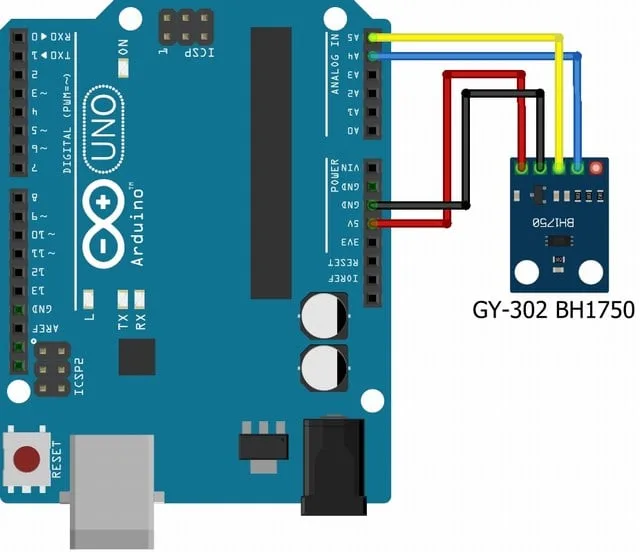
Wiring and Connections
| GY-302 Pin | Arduino UNO Pin | Function |
|---|---|---|
VCC |
5V |
Power Supply |
GND |
GND |
Ground Reference |
SCL |
A5 (or dedicated SCL) |
I2C Clock Line |
SDA |
A4 (or dedicated SDA) |
I2C Data Line |
For the OLED Display (operating typically at address 0x3C):
- Connect
VCCto Arduino5V(or3.3Vdepending on module specs). - Connect
GNDto ArduinoGND. - Connect
SCLto ArduinoA5(sharing the bus with the GY-302). - Connect
SDAto ArduinoA4(sharing the bus with the GY-302).
Verification Step: I2C Scanner
Before uploading custom application sketches, it is best practice to verify physical connections using the standard i2c_scanner sketch available in the Arduino IDE examples. When executed, the Serial Monitor should successfully identify two distinct addresses:
0x23(BH1750 Light Sensor)0x3C(SSD1306 OLED Display)
Software Dependencies
To compile and run the project code successfully, ensure the following libraries are installed via the Arduino IDE Library Manager:
- BH1750 Library (by Christopher Laws)
- Wire Library (included natively in the Arduino IDE)
- Adafruit SSD1306 (for driving the OLED screen)
- Adafruit GFX Library (core graphics engine for the display)
Practical Implications and Advanced Applications
The transition from analog light sensing to precision digital monitoring via sensors like the BH1750 opens up extensive design possibilities across multiple industries:
1. Smart Home Automation and Energy Efficiency
Automated lighting systems can dynamically adjust indoor illumination based on real-time ambient sunlight entering through windows. By integrating lux data into home automation hubs (such as Home Assistant via ESP32 nodes), motorized blinds and dimmable LED arrays can maintain optimal ergonomic workspace lighting while minimizing energy consumption.

2. Agriculture and Horticulture
In greenhouses, monitoring Photosynthetically Active Radiation (PAR) correlates closely with lux measurements for specific crop requirements. Automated shading systems can deploy when solar intensity exceeds threshold limits, protecting delicate seedlings from heat stress and excessive transpiration.
3. Consumer Electronics and UI Design
Modern smartphones, tablets, and desktop monitors utilize ambient light sensors to automatically scale screen brightness. Implementing a BH1750 in custom human-machine interfaces (HMIs) ensures that display readability remains optimal across varying environmental lighting conditions—from pitch-dark rooms to glaring daylight.
Conclusion
The BH1750 sensor, packaged efficiently on the GY-302 breakout board, stands out as a reliable, highly accurate, and cost-effective solution for ambient light measurement. As demonstrated through testing setups with the Arduino UNO and OLED displays, its native I2C communication protocol streamlines wiring complexity while delivering professional-grade lux data. Whether utilized in simple educational desktop projects or scaled up into comprehensive IoT weather monitoring networks, the BH1750 remains an essential tool in any maker’s electronics toolkit.
For complete schematics, deep-dive technical notes, test videos, and source code archives, consult the original project documentation provided by AdriRobot.