Understanding, Testing, and Deploying Buzzer Modules: A Comprehensive Technical Deep Dive into Active vs. Passive Audio Signaling Components
By Tech & Hardware Desk
In the vast ecosystem of DIY electronics, microcontrollers, and embedded systems, user feedback is rarely limited to visual indicators like LEDs. When a device needs to signal an impending hazard, confirm a successful command input, or announce the expiration of a programmed timer, developers almost universally turn to acoustic signaling devices. Among these, electronic buzzer modules remain a cornerstone of prototyping and product development.
Recent hardware testing conducted by technical documentation and prototyping platform AdriRobot has shed light on the functional nuances, electrical profiles, and implementation strategies of four prominent buzzer modules: the KY-006, KY-012, Keyestudio Ks0018, and Keyestudio Ks0019. Tested across multiple platforms—including the ubiquitous Arduino UNO, a specialized Multi Test Shield, and the beginner-friendly BBC micro:bit board—these modules highlight the critical distinctions between active and passive acoustic topologies.
This comprehensive report breaks down the core mechanics of buzzer modules, analyzes comparative hardware architectures, details multi-platform testing methodologies, and explores the broader implications for modern electronics prototyping.
1. Main Facts: Demystifying Acoustic Signaling Hardware
At its fundamental level, a buzzer module is an audio signaling device designed to convert electrical signals into audible sound waves. These devices can be constructed mechanically, electromechanically, or via piezoelectric elements. However, in modern embedded prototyping, piezoelectric and electromagnetic topologies dominate.
Active vs. Passive: The Core Operating Principle
The single most important distinction in buzzer module selection is whether the component is active or passive:

- Active Buzzer Modules (e.g., KY-012, Ks0018): These modules feature an internal oscillator circuit. When operating an active buzzer, the developer does not need to generate an audio frequency externally. Simply applying a direct current (DC) voltage to the signal pin initiates the internal oscillator, immediately producing a constant, pre-determined tone. They are the acoustic equivalent of a digital output pin switching an LED on or off.
- Passive Buzzer Modules (e.g., KY-006, Ks0019): These modules lack an internal oscillator. Consequently, they are entirely dependent on the host microcontroller to supply an alternating control signal—typically a square wave ranging between 2 kHz and 5 kHz. By varying the frequency and duty cycle of this square wave, developers can command passive buzzers to produce distinct musical notes, complex melodies, and variable frequency sweeps.
Piezoelectric vs. Electromagnetic Technologies
Beyond active and passive classifications, the underlying acoustic transducer technology dictates use-case suitability:
- Piezoelectric Buzzers: Constructed using a ceramic disc bonded to a metallic layer, piezoelectric buzzers are celebrated for their mechanical robustness, cost-effectiveness, and reliability. Because of their frequency response profile, they are widely deployed for narrow-band alarm signals, such as error alerts in household appliances and clinical safety warnings in medical technology.
- Electromagnetic Buzzers: These utilize an electromagnetic coil and a flexible metal diaphragm. When electrical current passes through the coil, it generates a magnetic field that forces the diaphragm to vibrate. Many modern electromagnetic variants integrate internal driving electronics to smooth out control requirements.
2. Chronology: The Testing Methodology and Evaluation Pipeline
To understand how these components perform in real-world scenarios, AdriRobot structured a rigorous, step-by-step evaluation pipeline spanning multiple hardware generations and microcontrollers.
Phase 1: Benchmarking Basic Form Factors (KY-006 & KY-012)
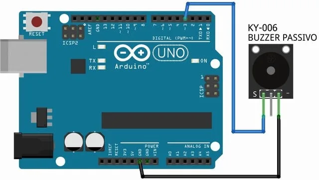
The evaluation began with the foundational KY-006 (passive) and KY-012 (active) modules. Because these modules share a minimalist circuit design consisting only of a pin connector and the buzzer element itself, researchers analyzed their direct electrical load on the host microcontroller. Utilizing only Ground (GND) and a single signal pin, these modules draw their operational current directly from the driving digital pin of the Arduino UNO. Each unit measures a compact 15 × 19 × 9 mm and weighs a mere 2.4 grams.
Phase 2: Evaluating Transistor-Buffered Modules (Ks0018 & Ks0019)
Next, the testing chronology advanced to more robust, integrated modules from Keyestudio: the Ks0018 (active) and Ks0019 (passive). Recognizing that driving a buzzer directly from a microcontroller pin can risk current overloads or voltage dropouts, Keyestudio incorporated discrete transistor switching into these boards. Researchers mapped the circuit topology to document how the component layout altered current draw and pin safety.
Phase 3: Platform Integration (Arduino, Multi Test Shield, and micro:bit)
The final phase of the testing timeline involved cross-platform deployment:
- Arduino UNO Direct Wiring: Basic square-wave generation using raw code and the native
tone()library. - Multi Test Shield Integration: Testing the KY-012 module plugged directly into the JP2 header of a custom Arduino R3-compatible shield designed for the 37-in-1 sensor kit, complete with real-time status updates piped to an onboard OLED display.
- BBC micro:bit Deployment: Interfacing the Ks0018 and Ks0019 modules with a micro:bit via a Keyestudio Sensor V2 shield, programmed utilizing block-based logic within the MakeCode environment.
3. Supporting Data: Comparative Hardware Analysis
A deep dive into the physical and electrical specifications of the four evaluated modules reveals clear trade-offs between simplicity, protection, and board footprint.

| Module Name | Type | Transistor Circuitry | Pins Required | Dimensions | Weight | Primary Driving Method |
|---|---|---|---|---|---|---|
| KY-006 | Passive | None (Direct Drive) | 2 (GND, Signal) | 15 × 19 × 9 mm | 2.4 g | Microcontroller square wave / tone() |
| KY-012 | Active | None (Direct Drive) | 2 (GND, Signal) | 15 × 19 × 9 mm | 2.4 g | High/Low DC digital level |
| Keyestudio Ks0018 | Active | Yes (NPN S8050) | 3 (GND, Signal, VCC) | 30 × 20 × 10 mm | 3.0 g | 3.3V / 5V VCC with transistor switch |
| Keyestudio Ks0019 | Passive | Yes (NPN S8050) | 3 (GND, Signal, VCC) | 30 × 20 × 10 mm | 3.0 g | External frequency + transistor switch |
Circuit Architecture: The Role of the NPN S8050 Transistor
A critical technical takeaway from the AdriRobot evaluation concerns the architectural disparity between the basic KY series and the Keyestudio Ks series.
While the KY-006 and KY-012 rely entirely on the microcontroller pin to source or sink operating current, the Keyestudio Ks0018 and Ks0019 integrate an NPN S8050 transistor acting as a high-speed electronic switch. In this configuration:
- The control pin from the microcontroller is connected exclusively to the base of the transistor via a current-limiting base resistor.
- The main operating voltage (3.3V or 5V) and the buzzer itself are isolated on the collector-emitter circuit, supported by an additional series resistor.
- The engineering benefit: The microcontroller pin is no longer burdened with supplying the operational current for the sound-producing element. It merely supplies a minuscule control current to switch the transistor, heavily protecting sensitive microcontrollers from inductive voltage spikes and excessive current draws.
4. Implementation and Programming Insights
Operating these modules requires distinct software paradigms depending on whether an active or passive variant is selected. AdriRobot’s documentation provides clear pathways for both.
Programming Passive Modules: Manual Waves vs. tone()
Working with passive modules like the KY-006 or Ks0019 requires generating an oscillating frequency. Developers have two primary methods within the Arduino IDE:
- Manual Square Wave Generation: By toggling a digital pin (e.g., Pin 3) between
HIGHandLOWstates with deliberate microscopic pauses, a developer constructs a custom square wave entirely in software. - The Native
tone()Function: A far cleaner, hardware-abstracted approach utilizes thetone(pin, frequency, duration)command. This function automatically generates a square wave with a stable 50% duty cycle on the specified pin for a designated period.
Programming Caveat: The Arduino tone() function operates under a strict single-channel limitation: it can produce only one tone at a time globally. Attempting to initiate a tone on a second pin while another is active has no effect, while calling tone() on the same active pin alters its current frequency on the fly. To silence the buzzer, developers invoke noTone(pin).
In AdriRobot’s reference application, the passive buzzer cycles through a 500 Hz tone and a 1000 Hz tone for one second each, followed by a mandatory five-second silence interval.

Programming Active Modules: Binary Logic
Active modules (KY-012, Ks0018) drastically simplify code requirements. Because the internal oscillator handles frequency generation, the programming logic mimics basic digital output management:
- Writing a
HIGHlevel to the signal pin initiates the internal oscillator, immediately starting the acoustic alert. - Writing a
LOWlevel cuts power or breaks the switching circuit, instantly silencing the module.
5. Implications for the Prototyping and Maker Community
The findings published by AdriRobot carry several important implications for educators, hobbyists, and professional prototype engineers working with modular sensor kits.
1. Circuit Safety and Component Longevity
Beginner electronics projects frequently fall into the trap of connecting inductive or audio loads directly to microcontroller General-Purpose Input/Output (GPIO) pins. While low-cost microcontrollers like the Arduino UNO feature internal clamping diodes, driving raw buzzers directly over extended periods can degrade pins or cause unexpected microcontroller resets due to voltage sag. The inclusion of transistor-buffered designs—such as those found in the Keyestudio Ks0018 and Ks0019—sets a best-practice standard for modular peripheral design, ensuring that sensitive logic boards remain completely isolated from load-side electrical stress.
2. Cross-Platform Versatility
The successful deployment of these buzzer modules across disparate architectures—from traditional 8-bit AVR microcontrollers (Arduino UNO) to specialized education hardware (BBC micro:bit via MakeCode blocks) and integrated test shields—demonstrates the universal nature of basic input/output components. For STEM educators, utilizing modular sensors that bridge multiple ecosystems lowers the barrier to entry, allowing students to transition seamlessly from block-based programming to low-level C/C++ development without needing to repurchase peripheral hardware.
3. Sourcing and Ecosystem Availability
For developers looking to integrate these components into their own builds, individual units remain widely accessible. The passive buzzer module KY-006 and the active buzzer module KY-012 are available individually. Furthermore, both variants are commonly bundled within comprehensive comprehensive prototyping bundles, such as the box of 37 sensors for Arduino, Raspberry Pi, and robotics.
For those seeking to review the underlying source code, complete wiring schematics, MakeCode programs, and expanded project ideas, the original technical documentation and testing report by AdriRobot serves as an invaluable, open-access resource for the global maker community.