Building a Smart Access Control System: An In-Depth Guide to Arduino-Powered RFID and NFC Technology
Main Facts: The Evolution of Secure, Proximity-Based Access Control
In an era where convenience and security intersect at the turn of a card, Radio Frequency Identification (RFID) and Near Field Communication (NFC) technologies have quietly revolutionized how we interact with our physical environments. From corporate turnstiles and residential apartment gates to transit systems, automated vending machines, and gym lockers, passive wireless transponders have become ubiquitous daily accessories.
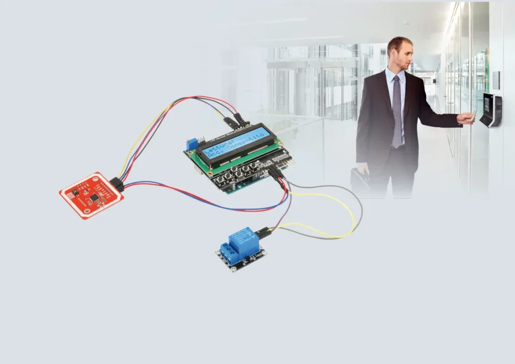
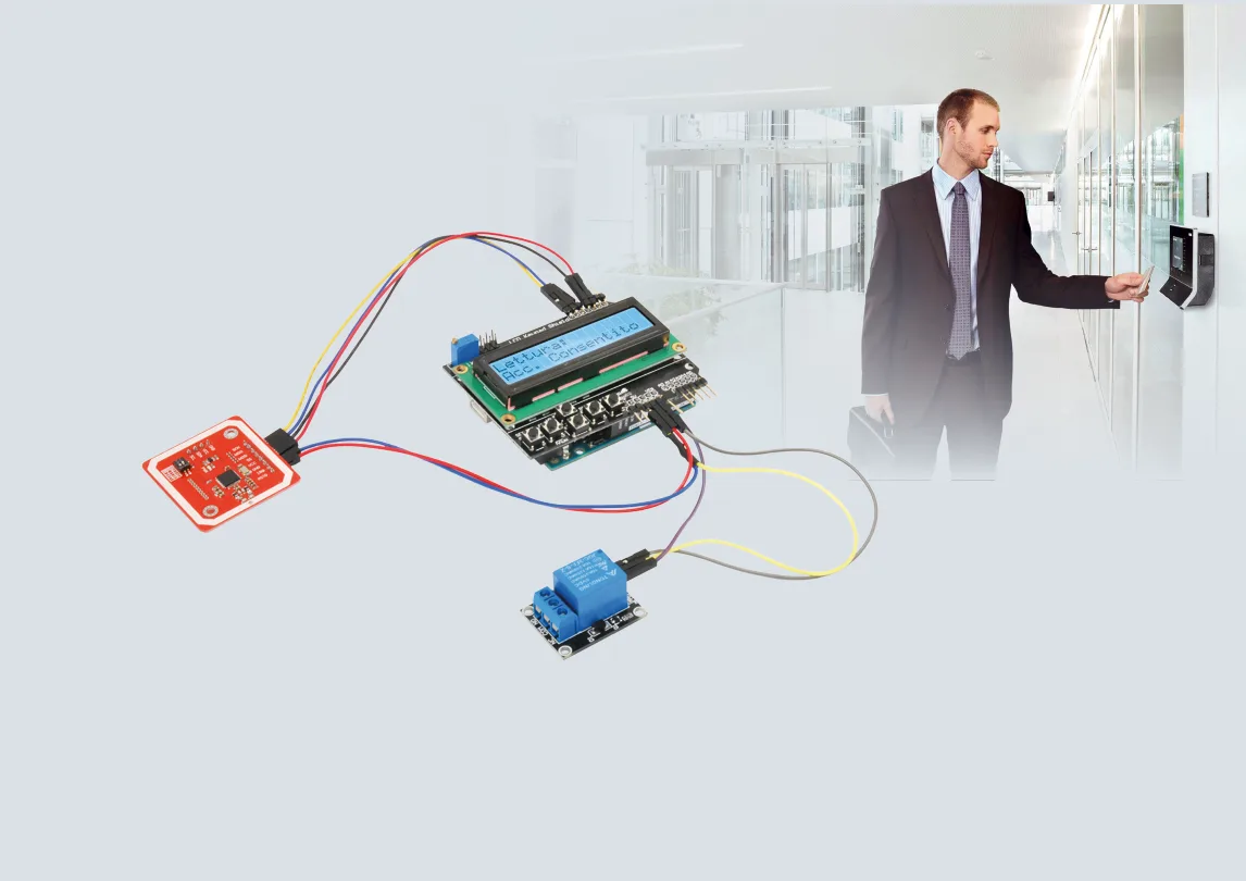
Capitalizing on this widespread infrastructure, modern makers and embedded systems engineers can now build sophisticated, enterprise-grade access control solutions using accessible hardware. This project details the design and deployment of a programmable electronic transponder lock built around an Arduino Uno, an LCD Keypad Shield, a 5V relay module, and the versatile PN532 NFC/RFID breakout board.

Designed to serve both as a standalone functional security device and as an educational development platform, this system detects, reads, and verifies passive and active transponders. When a recognized, pre-paired RFID tag or NFC card is scanned within a range of 30 to 70 millimeters, the Arduino triggers a relay switch—ideal for activating motorized doors, electronic strikes, or security gates.
Chronology: Understanding the Physics and Mechanics of RFID/NFC
To fully grasp how the project operates, it is essential to trace the sequential workflow of a passive RFID interaction from the moment a user presents a card to the final execution of an access decision.

Phase 1: The Electromagnetic Excitation
Unlike active transponders that carry their own internal power source, passive RFID and NFC tags are entirely dormant until they enter an electromagnetic field. The core of this process relies on the PN532 reader module, which features an integrated printed circuit board (PCB) coil.
When powered, the module’s exciter circuit generates a localized low-frequency electromagnetic field—typically operating at 13.56 MHz for ISO/IEC 14443 compliant systems or lower for specific legacy applications. This tight transmission window is intentionally constrained to a few centimeters to mitigate the risk of fraudulent data interception or unauthorized "skimming" by malicious actors.

Phase 2: Induction and Power Generation
As the passive tag enters the inductive field, Faraday’s law of induction takes effect: an alternating voltage is induced in the tiny copper coil embedded inside the card or key fob.
- Rectification: A high-speed onboard diode rectifies the alternating induced voltage into direct current (DC).
- Energy Storage: The rectified current charges a microscopic capacitor, storing sufficient electrical energy to briefly power the tag’s internal integrated logic.
- Data Transmission: Once energized, the tag’s internal encoder generates a globally unique identification (UID) code.
Phase 3: Load Modulation and Detection
Because the tag has no independent transmitter to broadcast its ID back to the reader, it uses a clever technique known as load modulation.

The encoder drives the base of an internal transistor. At every logic-high interval, the transistor conducts, electrically "loading" the tag’s internal coil. This action creates a measurable ripple effect in the reader’s exciter coil, causing a momentary spike in current draw.
A sense resistor in the reader circuit detects these micro-pulses, reconstructing the unique digital signature produced by the tag’s encoder. Throughout this cycle, the diode prevents the capacitor from prematurely discharging, ensuring the tag remains powered long enough to complete the data handshake.

Supporting Data: Hardware Architecture and Technical Specifications
Building this access control lock requires precise hardware integration. The project relies on off-the-shelf components available through electronic suppliers such as Futura Elettronica.
Core Component Breakdown
- Microcontroller: Arduino Uno (the central processing and logic unit).
- User Interface: LCD Shield equipped with an alphanumeric display and integrated navigational buttons (SELECT, LEFT, UP, DOWN, RST).
- Sensor Module: PN532 NFC/RFID Reader/Writer breakout board (featuring an integrated antenna, support for I²C, SPI, and High-Speed UART (HSU) communication interfaces).
- Actuator: 5V single-channel relay module.
- Power Supply: External 9V to 10V DC mains power supply capable of delivering at least 500 mA.
The PN532 Module and Communication Flexibility
The PN532 stands out for its multi-protocol versatility. Measuring just 43x41x4 mm, it operates on a flexible voltage range of 3.3V to 5V and supports multiple data interfaces selectable via onboard dip-switches:

- I²C Bus: Utilizes a streamlined 4-pad row (SCL, SDA, GND, VCC).
- SPI Bus: Utilizes an 8-pad row providing dedicated hardware lines (SCK, MISO, MOSI, SS, VCC, GND, RST0, and an Interrupt request pin, IRQ). The IRQ pin is particularly useful as it signals the Arduino instantly whenever a card enters the field, eliminating the need for constant polling.
Supported Card Standards
The system is compatible with an extensive array of high-frequency transponders, ensuring broad user convenience:
- Mifare Family: Mifare 1k, 4k, Ultralight, and DesFire cards (widely utilized standards developed by NXP Semiconductors).
- ISO/IEC Standards: ISO/IEC 14443-4 compliant cards (including CD97BX, CD light, and P5CN072 SMX).
- Specialized Formats: Innovision Jewel cards (such as the IRT5001) and FeliCa contactless cards (RCS_860 and RCS_854).
Official Operational Modes: Firmware Logic and User Interface
Managed by an optimized Arduino sketch and an Adafruit PN532 management library, the system provides a robust user interface displayed on the LCD Shield. Upon boot-up, the screen prompts the user with "Access Card Reader" followed by a continuous "Lettura: Lettura in corso" (Reading in progress) prompt.

Navigating via the shield’s physical buttons reveals three core operational modes:
1. Read Mode (Normal Operation)
When a user presents a transponder, the system compares the scanned UID against authorized records stored in the Arduino’s memory:

- Access Granted: If a match is found, the display reads "Acc. Consentito", and digital pin 11 goes HIGH for 2 seconds, energizing the relay module to trigger the electronic strike.
- Access Denied: If the UID is unrecognized, the display returns "Acc. Negato", and the relay remains idle.
2. Edit Mode (Tag Registration and Deletion)
Administrators can program new keys directly at the device level without needing a connected PC:
- Adding a Tag: Selecting Edit Mode prompts the user to wave a new tag within 7 cm of the PN532 module. The system reads the UID and saves it to non-volatile memory, confirming with "TESSERA SALVATA".
- Toggling Deletion: If a previously registered tag is scanned while the system is kept in Edit Mode, the firmware automatically purges its UID from the database, displaying "TESSERA RIMOSSA".
3. Delete Mode (Memory Purge)
For complete security resets, Delete Mode allows an administrator to wipe the entire database of authorized tags simultaneously, returning the system to a clean slate.

// Example Snippet: Core Read and Authorization Logic
if (success)
    cardid = getCardIdAsInt(uid, uidLength);
    int32_t findUid = findRfidInEeprom(uidLength, uid);

    if (findUid != -1)
        // Card authorized: Trigger relay for 2 seconds
        lcd.setCursor(0, 1);
        lcd.print("Acc. Consentito");
        digitalWrite(11, HIGH);
        delay(2000);
        digitalWrite(11, LOW);
     else
        // Access denied
        lcd.setCursor(0, 1);
        lcd.print("Acc. Negato");
        delay(2000);
Implications: Practical Applications and Customization Potential
While engineered primarily as an electronic transponder lock, the architecture of this project opens the door to numerous scalable applications in domestic automation and light commercial security.
Enclosure and Deployment Best Practices
For real-world deployment, engineers recommend housing the entire assembly inside a non-conductive plastic enclosure. Because radio frequency fields easily penetrate plastics and polymers, the PN532 reader module can be safely secured directly behind the front panel using silicone sealant without degrading signal detection or transmission ranges.

Firmware Customization and Expansion
The open-source nature of the Arduino platform invites developers to tailor the firmware to specific operational requirements:
- Acoustic and Visual Feedback: By tapping into the transistor circuit driving the relay, builders can easily integrate auxiliary buzzers or high-intensity warning LEDs in parallel to signal successful reads or forced-entry alerts.
- Extended Logging: With minor code modifications, user access logs containing timestamps and unique user IDs can be mirrored over the serial monitor or logged to an external SD card module.
- NFC Smartphone Integration: Beyond physical key cards, the PN532’s capability to interface with select Android smartphones running NFC card emulation software allows users to unlock doors directly using their mobile devices.
By merging affordable microcontrollers with robust contactless identification technology, this project demonstrates that enterprise-level security concepts remain entirely accessible to developers, hobbyists, and innovators alike.