Mastering the TP4056 Lithium Battery Charging Module: Design, Safety, and Practical Integration for Modern Electronics
Introduction: The Ubiquity of Lithium Power and the TP4056 Revolution
In the landscape of modern electronics, portable power is no longer a luxury; it is a foundational requirement. From Internet of Things (IoT) sensors deployed in remote agricultural fields to wearable health monitors, handheld instrumentation, and custom robotics, single-cell 3.7V Lithium-Ion (Li-Ion) and Lithium-Polymer (Li-Po) batteries reign supreme. They offer high energy density, low self-discharge rates, and a favorable weight-to-power ratio.
However, managing these power sources safely requires precision engineering. Overcharging a lithium cell can lead to thermal runaway, venting, or catastrophic failure, while deep discharge permanently damages the chemistry, reducing capacity or rendering the cell entirely useless.
Enter the TP4056 module. Ubiquitous, cost-effective, and surprisingly sophisticated, this tiny circuit board has become the go-to solution for hobbyists, engineers, and prototype developers looking to implement reliable lithium battery charging. While basic iterations of the module have long populated the maker ecosystem, recent technical breakdowns—such as those detailed by electronics resource AdriRobot—highlight the critical importance of variants equipped with comprehensive protection circuitry.
This deep-dive technical overview explores the architecture, variants, operational phases, safety schematics, and practical hookups of the protected TP4056 module, providing a masterclass in integrating safe lithium power into projects ranging from Arduino to advanced IoT deployments.
Main Facts: Anatomy and Core Specifications of the Protected TP4056
At its core, the TP4056 is a complete constant-current/constant-voltage (CC/CV) linear charger for single-cell lithium-ion batteries. Measuring a mere 22 × 17.3 × 3.6 mm and weighing roughly 2 grams, the standard module packs an impressive array of functions into a footprint smaller than a postage stamp.
Key Technical Specifications
- Input Voltage Range: 4.0V to 8.0V (Standard 5V via Micro-USB or USB Type-C interface).
- Target Battery Chemistry: Single-cell 3.7V/3.6V Li-Ion and Li-Po cells (such as the ubiquitous 18650 format).
- Default Charge Current: 1A (adjustable via an external programming resistor).
- Charging Precision: Preset to 1.5% accuracy at 4.2V full-charge threshold.
- Operational Temperature Range: -10°C to +85°C.
- Status Indicators: Dual-LED interface (Red for charging, Blue/Green for charge complete).
- Protection Add-ons (Protected Variant): Integrated DW01A protection IC and FS8205A dual N-channel MOSFET.
Unlike the stripped-down, bare-bones iterations of the charger, the protected version addresses lithium’s inherent volatility by interposing a dedicated guardian circuit between the power source, the battery cell, and the connected load.
Chronology and Evolution: From Barebones Charging to Intelligent Protection
The journey of the TP4056 module mirrors the evolution of the maker movement itself—shifting from raw, component-level integration toward modular, user-friendly, and fail-safe sub-assemblies.
Phase 1: The Raw Linear Controller Era
In early iterations, the TP4056 IC was deployed primarily on custom PCBs or bare modules designed solely to manage the charging cycle. These boards excelled at the CC/CV charging algorithm but lacked downstream safety features. If a load drew too much current, or if a battery was accidentally shorted or drained past its safe voltage threshold (typically around 2.4V to 2.8V), the battery was left entirely unprotected. Developers had to manually integrate battery management systems (BMS) upstream or downstream, complicating designs.

Phase 2: The Integration of the DW01A and Dual MOSFETs
Recognizing the high rate of user error and the inherent hazards of unprotected lithium cells, manufacturers began pairing the TP4056 chip with the DW01A battery protection IC and an accompanying dual MOSFET package (such as the FS8205A or HM5434). This dual-chip architecture transformed the module from a simple battery charger into a miniature, self-contained Battery Management System (BMS).
Phase 3: Modern Variations (USB-C and Step-Up Converters)
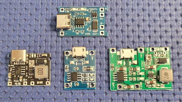
Today, the ecosystem has diversified further. While Micro-USB inputs were standard for years, modern iterations widely incorporate robust USB Type-C connectors to match contemporary cabling standards. Furthermore, engineering variants have emerged:
- The MT3608 Step-Up Hybrid: Some boards integrate an MT3608 DC-DC boost converter, allowing the 3.7V battery output to be stepped up to adjustable voltages ranging from 4V to 28V.
- Non-Protected Variants: Modules like the J5019 (HW-357) retain the raw charging capability without protection circuitry, intended for applications where an external BMS is already present.
- Advanced Protected Modules: Boards featuring enhanced companion ICs like the HM5434 continue to push the boundaries of reliability and thermal management.
Supporting Data: Understanding the CC/CV Algorithm and Circuit Schematics
To effectively deploy the TP4056 in professional or hobbyist hardware, one must understand the electrical mechanics governing its operation.
The Three-Phase Charging Cycle
Lithium-ion batteries cannot be charged simply by applying a flat voltage; doing so can cause overheating or chemical degradation. The TP4056 utilizes a strict CC/CV protocol executed in three distinct phases:
- Trickle Charge (Pre-Charge) Phase: When a battery is deeply discharged (terminal voltage dropping below approximately 2.9V), the module enters a safety pre-charge state, delivering a reduced current (typically 10% of the set charge current). This gently brings the cell voltage back up to a safe operating window without stressing the chemistry.
- Constant Current (CC) Phase: Once the cell voltage exceeds ~2.9V, the module ramps up delivery to the full programmed charge current (preset to 1A). During this phase, the battery voltage steadily rises while the current remains locked at its maximum programmed level.
- Constant Voltage (CV) Phase: As soon as the battery terminal voltage reaches the precise threshold of 4.2V, the module enters the constant voltage phase. The voltage is held strictly at 4.2V while the charging current naturally and gradually tapers off. Once the current drops to roughly 10% of the programmed value (or the termination threshold, typically 1/10th of the set current), the charge cycle terminates, and the status LED shifts from red to blue/green.
Schematic Breakdown: TP4056, DW01A, and FS8205A
A close examination of the protected module’s schematic reveals how these components interact:
- The TP4056 Controller: Acts as the primary linear charging engine. Pin 2 ($R_PROG$) determines the charging current via an external resistor. A stabilizing 0.1 µF ceramic capacitor sits near the VCC pin to filter noise, while dual status pins drive the charge/standby LEDs through 1 kΩ current-limiting resistors.
- The DW01A Protection IC: Monitors the voltage across the battery connected to terminals B+ and B-. It watches continuously for three critical faults:
- Overcharge Voltage: Typically triggered if the cell voltage exceeds ~4.3V.
- Over-discharge Voltage: Triggered if the cell voltage plummets below ~2.4V.
- Overcurrent/Short Circuit: Triggered if the discharge current exceeds safe operational limits or if a direct short occurs on the output.
- The FS8205A Dual MOSFET: Acting as the electronic gatekeeper, this dual N-channel MOSFET package is controlled directly by the DW01A. When a fault condition is detected, the DW01A switches off the MOSFETs, cleanly disconnecting the load and isolating the battery from further harm. Once normal conditions are restored (e.g., a short is removed or charging resumes), the circuit automatically reactivates.
Terminal Mapping and Correct Wiring
The protected TP4056 board features three distinct pairs of connection terminals, and respecting their layout is vital for proper operation:
- IN+ and IN-: Takes the 5V DC supply (an alternative to feeding power via the onboard USB port).
- B+ and B-: Direct connection points for the positive and negative terminals of the 3.7V Li-Ion/Li-Po cell.
- OUT+ and OUT-: Regulated and protected power output terminals that feed the downstream load (microcontroller, sensors, actuators).
Crucial Engineering Rule: The load must always be connected to OUT+ and OUT-, never directly to B+ and B-. Connecting a load directly to the battery bypasses the DW01A protection circuit entirely, leaving the system vulnerable to over-discharge and short-circuit damage.
Customizing the Charge Current ($R_PROG$)
The module ships factory-configured to a 1A charge rate via an onboard $R3$ resistor ($R_PROG$) valued at 1.2 kΩ. However, charging a small 500 mAh Li-Po battery at 1A will rapidly degrade its lifespan.

The charge current is governed by the formula:
$$IBAT = frac1000RPROG quad text(or more precisely, I = fracVPROGRPROG times 1200 text where V_PROG = 1V text)$$
By swapping out the programming resistor, developers can tailor the current to the battery capacity:
- 1.2 kΩ resistor: ~1000 mA (Ideal for large 18650 cells rated 1500–3000 mAh)
- 2.0 kΩ resistor: ~580 mA
- 3.0 kΩ resistor: ~400 mA
- 5.0 kΩ resistor: ~250 mA
- 10.0 kΩ resistor: ~130 mA (Ideal for small wearable Li-Po cells rated under 500 mAh)
Official Responses and Engineering Best Practices
While open-source hardware communities and component distributors like AdriRobot and Open Electronics champion the TP4056 for its versatility, electronics engineers emphasize adherence to strict operational guidelines to mitigate thermal and electrical risks.
Thermal Management at 1A
Operating a linear charging controller at its maximum 1.0A rating in a 5V-to-4.2V conversion scenario generates localized thermal dissipation ($PD = (VIN – VBAT) times IBAT$). With a 5V input and a drained 3.0V battery drawing 1.0A, the linear regulator dissipates approximately $(5 – 3) times 1 = 2textW$ of heat. Because the standard breakout board is small, the TP4056 chip can become uncomfortably hot to the touch.
Official Recommendation: When operating at or near 1A continuous charging, ensure the module is mounted in a well-ventilated enclosure. If thermal shutdown occurs (internal thermal protection kicks in around 145°C), the charging current will automatically scale back. For enclosed, thermally constrained spaces, increasing $R_PROG$ to lower the charge current to 500 mA or lower is strongly advised.
Simultaneous Charging and Powering Loads
A common design temptation is to run a power-hungry peripheral (such as a DC motor, cellular modem, or high-power LED array) from the output terminals while the battery is actively charging.
Official Recommendation: Avoid driving heavy, dynamic loads during the active charging phase. High current draw can distort the current-sensing feedback loop, confusing the TP4056 and preventing it from accurately detecting the end-of-charge (EOC) state. This can lead to prolonged exposure to the constant voltage phase, accelerating battery wear.
Implications: Practical Hookups and Integration with Modern Microcontrollers
The true power of the protected TP4056 module lies in its seamless integration into autonomous, battery-powered electronic ecosystems.

1. Powering Low-Voltage Microcontrollers (ESP8266, ESP32-C3, STM32)
A single Li-Ion cell operates across a voltage range of 4.2V fully charged down to ~3.0V fully depleted. Many modern 3.3V microcontrollers and IoT sensors cannot tolerate a direct 4.2V input safely, nor will they operate reliably as the battery voltage sags below 3.3V.
The Solution: Feed the OUT+ and OUT- terminals into a dedicated ultra-low-quiescent-current DC-DC step-down/step-up (buck-boost) converter or a stable 3.3V low-dropout (LDO) regulator (such as the CN3903 or similar topology). This guarantees a rock-solid 3.3V supply to your ESP32-C3 or STM32 MCU regardless of whether the battery is fresh at 4.2V or nearly exhausted at 3.1V.
2. Custom Power Banks and Instrumentation
For portable instrumentation requiring higher voltages (e.g., 5V, 9V, or 12V), routing the OUT+ and OUT- terminals into an adjustable MT3608 step-up booster module allows makers to build custom, protected power banks tailored to precise project voltage requirements.
3. Smart Monitoring via Arduino and IoT
Beyond merely supplying power, the TP4056 module offers hardware telemetry hooks. By connecting the CHRG (Pin 7) and STDBY (Pin 6) status pins of the TP4056 to digital input pins on an Arduino UNO or an ESP32-C3 microcontroller, software can track battery status in real-time:
- CHRG pin pulled LOW: Charging is currently in progress.
- STDBY pin pulled LOW: Charging cycle is complete (battery fully charged).
- Both pins HIGH: No power applied, or battery disconnected/fault state.
When paired with a Wi-Fi-enabled microcontroller like the ESP32-C3, these status pins—combined with a simple voltage divider on the battery terminal for state-of-charge (SoC) estimation—allow developers to deploy remotely monitored, battery-health-aware IoT edge nodes that report their power status directly to cloud dashboards.
Troubleshooting Guide
If you encounter unexpected behavior during your build, consult this rapid diagnostic checklist:
- Battery refuses to charge: Check the input voltage on the VCC/IN pins (must be stable between 4.0V and 8.0V). Verify that the battery is connected with correct polarity to B+ and B-. Ensure the battery voltage is not below the DW01A protection lockout threshold (if a cell drops below ~2.4V, the protection circuit may trip permanently until a brief charge wakes it up).
- Module overheats excessively: You are likely drawing the full 1.0A charge current into a small battery or operating in a confined space. Swap out $R3$ ($R_PROG$) for a higher resistance value (e.g., 3 kΩ or 5 kΩ) to reduce the charge current.
- Load shuts down unexpectedly during operation: Verify that your load is connected to OUT+ and OUT-, not B+ and B-. If the load draws a sudden surge current exceeding the DW01A threshold (typically 2A to 3A), the protection circuit will instantly trip, cutting power to protect the system.
Conclusion
The protected TP4056 lithium battery charging module represents a masterclass in accessible power electronics. By intelligently marrying linear charging control with robust overcharge, deep-discharge, and short-circuit protection, it bridges the gap between raw chemical energy and reliable circuit design. Whether you are constructing a wireless environmental monitor with an ESP32, prototyping an Arduino-based field instrument, or engineering a custom portable power bank, understanding the nuances of the TP4056’s thermal profile, programming resistors, and output wiring ensures your devices remain safe, efficient, and durable for years to come.