The Timeless 555 Timer Strikes a Chord: How to Build a Classic Mini Electronic Piano
BERLIN — In an era dominated by complex microcontrollers, programmable system-on-chip architectures, and sophisticated software synthesizers, the humble 555 timer continues to prove that simplicity never goes out of style. First introduced by Signetics in 1971, the 8-pin integrated circuit has been used in everything from kitchen timers and pulse-width modulators to makeshift police sirens. Now, electronics hobbyists and educators have a fresh way to celebrate the iconic chip: a fully functional, single-octave mini electronic piano built entirely around traditional, through-hole components and a classic astable multivibrator circuit.
Designed for beginners, electronics experimenters, and younger hobbyists taking their first steps into hardware engineering, this minimalist project transforms a basic network of resistors, capacitors, and pushbuttons into a monophonic musical instrument. Etched onto a custom printed circuit board (PCB) shaped like a piano keyboard, the device delivers an engaging, hands-on introduction to analog timing, frequency calculation, and audio output stages without requiring a line of code or a single surface-mount device (SMD).
Main Facts: Engineering Nostalgia with the Ultimate Versatile IC
The core of the mini electronic piano relies on the NE555 integrated circuit configured as an astable multivibrator—an oscillator circuit that continuously cycles between two quasi-stable states without external triggering.
The instrument features:
- Seven Basic Notes Plus High C: Eight normally open pushbuttons ($S_1$ through $S_8$) correspond to a diatonic scale spanning one full octave plus a high C (C, D, E, F, G, A, B, and high C).
- Monophonic Architecture: Utilizing a clever series resistor ladder rather than parallel branches, the circuit ensures that if multiple keys are pressed simultaneously, the instrument invariably plays the highest-frequency note, preventing dissonant chord clashes.
- Traditional Construction: Built exclusively with through-hole technology (THT) components, the project avoids the precision soldering challenges of SMD packages, making it accessible to classroom environments and home workshops alike.
- Direct Audio Drive: A moving-coil loudspeaker driven through an electrolytic decoupling capacitor translates the square-wave output of the 555 timer into audible, softened musical tones.
Chronology: The Evolution of the 555-Based Synth
While the 555 timer has populated hobbyist schematics for over half a century, its journey into audio generation spans several distinct technological eras:

- 1971: Hans Camenzind designs the NE555 timer for Signetics. Originally conceived as a stable timing and clock-generation circuit, electronics experimenters quickly realize its analog audio capabilities.
- 1970s–1980s: Early computing and hobbyist magazines publish rudimentary "Atari Punk Console" and simple organ schematics, cementing the 555 as an accessible sound-effects generator for science fairs and home electronics benches.
- 1990s–2000s: As microcontrollers like the PIC and AVR democratize digital synthesis, analog astable oscillators take a temporary backseat in educational curricula, though they remain favored for their instant startup and tactile feedback.
- Present Day: A renewed maker-movement appreciation for analog transparency and retro computing inspires projects like the mini electronic piano. Designers merge timeless solid-state logic with custom-shaped PCBs, blending aesthetic charm with fundamental electronics theory.
Supporting Data: Understanding the Circuit and Frequency Math
To fully appreciate how a timing chip generates music, one must examine the internal architecture of the NE555 and the mathematical formulas governing its oscillation.
The Astable Configuration
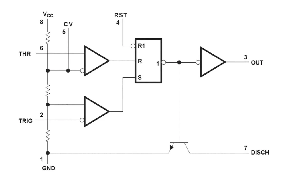
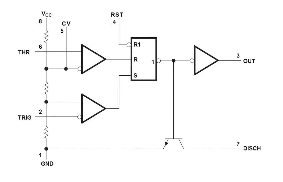
Inside the 555, an internal voltage divider composed of three equal resistors provides reference voltages to two internal comparators: $1/3$ of the supply voltage for the lower comparator (TRIG, pin 2) and $2/3$ for the upper comparator (THRESHOLD, pin 6). The outputs of these comparators feed an RS flip-flop, which in turn controls an internal output buffer (OUT, pin 3) and a discharge transistor (DISCH, pin 7).
At power-on, with capacitors discharged, pins 2 and 6 sit near zero volts. The lower comparator drives the flip-flop’s SET input high, forcing the output Q high and keeping the discharge transistor off. Timing capacitor $C_2$ begins charging through series resistors $R_1$ and $R_a$ (where $R_a$ represents the total resistance introduced by the pressed buttons).
Once the voltage across $C_2$ exceeds $2/3$ of the supply voltage, the upper comparator resets the flip-flop, pulling the output low and turning on the discharge transistor. $C_2$ then discharges through $R_a$ until its voltage drops below $1/3$ of the supply voltage, restarting the cycle.
Mathematical Frequency Calculation
The frequency ($f$) generated by the astable circuit depends directly on timing capacitor $C_2$, fixed resistor $R_1$, and the active button resistance $R_a$:

$$f = frac1.44C_2 cdot (R_1 + 2R_a)$$
Because the project employs a resistor ladder bypassed by the pushbuttons, pressing button $S_8$ (high C) inserts only resistor $R_5$ into the network. Utilizing a $0.1,mutextF$ capacitor ($C_2$), $R_1 = 1,textkOmega$, and $R_a = 10,textkOmega$:
$$f = frac1.440.1 times 10^-6,textF cdot (1000,Omega + 2(10,000,Omega)) = 685.7,textHz$$
Conversely, pressing button $S_1$ introduces the cumulative resistance of the entire ladder ($R_a = 23,textkOmega$), yielding the lowest frequency of the octave:
$$f = frac1.440.1 times 10^-6,textF cdot (1000,Omega + 2(23,000,Omega)) = 306.4,textHz$$

Intermediate buttons step through calculated resistance values adjusted to match standard E24 series resistor tolerances, ensuring accurate musical intervals without requiring variable tuning pots.
Waveform and Duty-Cycle Dynamics
The output of an astable 555 timer is fundamentally a square wave, characterized by a specific duty cycle ($dc$). The high-state pulse duration ($t_h$) and low-state pause duration ($t_l$) are calculated as:
$$t_h = 0.693 cdot (R_1 + R_a) cdot C_2$$
$$t_l = 0.693 cdot R_a cdot C_2$$
The duty cycle approaches $50%$ as $R_a$ significantly exceeds $R_1$. To prevent harsh, buzzy harmonic distortion typical of pure square waves, the output signal passes through an electrolytic decoupling capacitor ($C_4$) in series with the moving-coil loudspeaker ($LS_1$). Rather than simply blocking DC components, $C_4$ introduces exponential rise and fall edges during charging and discharging phases, effectively smoothing the waveform and providing a warmer, more organic acoustic timbre.

Official Responses and Educational Perspectives
Electronics educators and hardware designers have widely praised projects that bridge the gap between abstract textbook theory and tangible physical computing.
"In modern engineering education, students are frequently handed powerful development boards where everything is abstracted behind high-level libraries," notes Dr. Elena Vance, a senior lecturer in embedded systems at the Institute of Electrical Engineering. "Circuits built around foundational chips like the 555 force learners to look at differential equations, RC charging curves, and logic states directly on an oscilloscope. You can hear the math changing in real-time as you press a button."
Furthermore, open-source hardware advocates emphasize the accessibility of the design. Because the circuit eschews surface-mount components, builders of nearly any skill level can successfully populate the PCB with a standard soldering iron, basic wire cutters, and solder. The incorporation of a PCB shaped explicitly like a piano keyboard adds an engaging industrial design element that elevates the project from a generic utility board to a recognizable, functional novelty instrument.
Implications: The Enduring Legacy of Analog Simplicity
As the electronics landscape races toward hyper-integration, IoT connectivity, and artificial intelligence at the edge, simple analog projects occupy a vital space in technological culture.
- STEM Education Catalyst: By providing immediate, audible feedback, circuits like the 555 mini electronic piano maintain student engagement far more effectively than abstract simulations. Troubleshooting a silent speaker or an incorrect note teaches systematic debugging skills applicable to advanced engineering.
- Low Barrier to Entry: Global supply chain fluctuations and component shortages periodically impact microchip availability. The ubiquitous, multi-sourced 555 timer remains readily available, inexpensive, and resilient against obsolescence.
- Fostering Maker Creativity: Projects of this scale remind hobbyists that innovation does not always require massive computing power. By creatively combining basic passive components with active timing elements, makers can invent novel interfaces, instruments, and control systems using principles established over fifty years ago.
For seasoned engineers seeking a weekend nostalgia trip, or parents introducing children to the magic of hardware assembly, the 555-based mini electronic piano stands as a testament to elegant, timeless design—proving conclusively that with eight pins and a handful of resistors, anyone can make music.