Inside the Relay Room: Maker Peter’s 16-Bit Electromechanical Masterpiece Brings Computing Back to Its Industrial Roots
In an era dominated by silicon microchips packing billions of transistors onto fingernail-sized dies, where clock speeds are measured in gigahertz and artificial intelligence dictates the frontier of software, a counter-cultural movement thrives in the workshops of dedicated hobbyists. This subculture looks past the hyper-efficiency of modern microelectronics, choosing instead to commune with the raw, audible physics of computing.
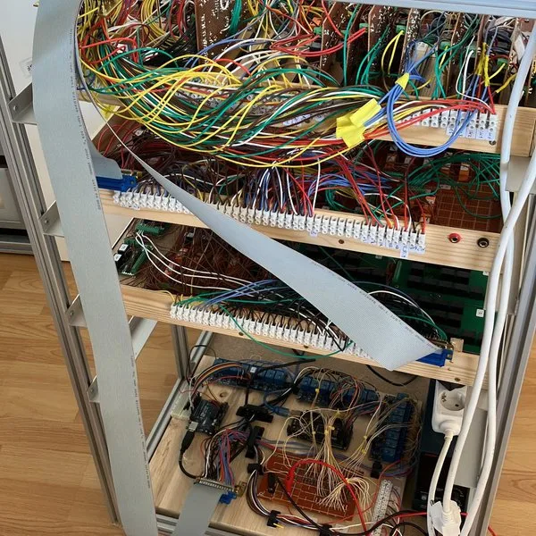
Enter Peter’s homebrew 16-bit relay computer—a monumental electromechanical marvel that trades microscopic gates for clicking, 24-volt self-holding relays. Far from a mere cosmetic art piece or a non-functional static display, this machine is a fully Turing-complete computer capable of executing complex routines. It crunches Pi to two decimal places, calculates the integer square root of 60,000, and maps out Dijkstra’s shortest path algorithm.
Blending mid-century telephone-exchange technology with modern rapid prototyping tools like FPGAs and Arduino microcontrollers, Peter has created a bridge between two vastly different epochs of engineering history. This deep dive explores the architecture, chronological development, supporting data, design philosophy, and broader technological implications of one of the most fascinating homebrew computing projects of the decade.
Main Facts: Architecture and Specifications of the Relay Computer
At its core, Peter’s machine is a custom-designed, accumulator-register 16-bit computer. Unlike modern processors that feature massive register files, superscalar pipelines, and out-of-order execution, this relay-based CPU channels the minimalist purity of early computers like the ENIAC or the IBM Card Programmed Calculator, albeit scaled down to a manageable workbench footprint.
The CPU and Instruction Set
The processing unit relies entirely on an accumulator-register (ACCU) topology. Every major arithmetic operation, logic manipulation, and load/store procedure must pass through this central accumulator. The instruction set architecture (ISA) consists of exactly 19 carefully chosen commands. Despite this modest vocabulary, the instruction set is remarkably versatile, supporting operations sophisticated enough to execute algorithmic logic typically reserved for far more powerful architectures.
Addressing Modes
To transcend simple linear code execution, the CPU implements three distinct addressing modes:
- Direct Value Loading (
LD X): The accumulator is loaded directly with the word located at the memory address immediately following the opcode. - Direct Memory Addressing (
LD M(X)): The CPU loads data from the specific address contained within the location following the opcode. - Indirect Addressing (
LD M(M(X))): The processor reads an address, looks up the value stored at that address, and uses that value as the final memory pointer.
By incorporating indirect addressing, Peter effectively gave his electromechanical creation the power of pointers and dynamic data structures, paving the way for complex tasks like table lookups and graph traversal algorithms.
Control Unit Mechanics
Control flow is managed via a Program Counter (PC) equipped with a dedicated hardware adder capable of performing a single operation: adding one. Because the modified program counter cannot directly write its own value plus one back into itself in a single step, Peter engineered an intermediate holding register dubbed PC_HR.
Subroutine management is handled via a dedicated Return Address register (SR). This register accommodates CALL and RET instructions, successfully executing a single level of subroutine nesting. With only 19 instructions in the playbook, a deep hardware stack was deemed unnecessary, keeping the relay count manageable while still fulfilling structural needs.
Peripherals and Input/Output
The system is far from an isolated processor; it features a robust I/O ecosystem. The machine boasts a 16-bit I/O register alongside a 16-port input register. Output visualization is handled by a vibrant 32×32 LED matrix display connected directly to the system’s output lines, giving onlookers a real-time window into the machine’s computational thoughts.
Chronology: From Concept to Electromechanical Reality
Building a computer out of industrial relays is not a weekend project; it requires a disciplined engineering chronology that spans simulation, iterative prototyping, structural design, and physical assembly.
Phase 1: Digital Simulation and Logic Validation
Before a single wire was stripped or a relay socket was screwed down, Peter tested the entire computer logic in virtual space. He utilized Logic World, an advanced simulation game frequently leveraged by digital logic hobbyists, to build, test, and refine the CPU architecture.
Concurrently, Peter developed complex Excel macros that acted as step-by-step software emulators. These spreadsheets allowed him to trace the execution of machine code instruction by instruction, inspecting register states and memory contents up to user-defined breakpoints.
As a final verification step before committing to physical hardware, Peter wrote VHDL code to emulate the relay system design on Field Programmable Gate Array (FPGA) development boards. This rigorous multi-stage validation process ensured that architectural bugs—such as race conditions in the control logic—were ironed out long before expensive hardware components were purchased.
Phase 2: Solving the 4-Pulse Clock Paradox
One of the most profound engineering hurdles in relay-based computing is state management. Unlike transistor-based CMOS logic, which switches states almost instantaneously and retains data through capacitance or static feedback, electromechanical relays have physical mass, mechanical lag, and distinct bounce characteristics.
Crucially, every register constructed from self-holding relays must be explicitly cleared before any new data write can occur. If a register is not cleared, old states bleed into new operations, corrupting calculations.
To solve this, Peter abandoned the concept of a standard, symmetrical digital clock signal. Instead, he engineered a four-pulse clock sequence. The clock cycle is meticulously choreographed into distinct phases: clear, prepare, load, and stabilize. This complex timing sequence had to be designed into the foundational logic rather than bolted on as an afterthought.
Phase 3: Hybrid Architecture Integration
Recognizing the physical limitations of mechanical relays—such as power consumption, heat generation, physical wear, and sheer board space—Peter adopted a hybrid design philosophy.
- The Electromechanical Core: The CPU data path, arithmetic logic unit (ALU) components, and core registers are constructed entirely from heavy-duty 24V electromechanical relays equipped with flyback diodes to suppress voltage spikes.
- The Solid-State Support System: Rather than building massive relay-based RAM arrays (which would have expanded the project from a workbench curiosity to room-filling infrastructure), Peter offloaded memory operations to an Arduino microcontroller. A second, independent Arduino was deployed to manage the intricate four-pulse clock generator.
This pragmatic division of labor kept the project within the financial and spatial reach of a standard home workshop, merging 1940s-era switching concepts with 21st-century microcontroller versatility.
Phase 4: Bench Testing and Benchmark Execution
Once physical assembly was complete, Peter subjected the machine to rigorous benchmark testing to prove its computational mettle.
- Calculating Pi: The machine was tasked with calculating the mathematical constant $pi$ to two decimal places. The relay computer chewed through the algorithm, consuming 1,377 instructions and taking a little over 8 minutes to reach the solution.
- Integer Square Root: When fed the number 60,000, the machine calculated its integer square root as 244. Expressed in the machine’s native binary language, the output reads
1111 0100. - Pathfinding Algorithms: Demonstrating that the architecture could handle advanced data structures, Peter successfully executed Dijkstra’s shortest path algorithm on the machine, proving its viability for non-trivial computational tasks.
Supporting Data: Performance Metrics and Hardware Breakdown
To truly appreciate the engineering feat of Peter’s 16-bit relay computer, it helps to examine the raw data regarding its performance, components, and operational constraints.
| Metric / Specification | Value / Description |
|---|---|
| Word Size | 16-bit |
| Relay Operating Voltage | 24 Volts DC |
| CPU Architecture | Accumulator-Register (ACCU) |
| Instruction Set Size | 19 distinct commands |
| Addressing Modes | Direct, Memory-Indirect, Pointer-Indirect (LD X, LD M(X), LD M(M(X))) |
| Clock Architecture | 4-pulse sequential cycle (Clear, Prepare, Load, Stabilize) |
| Memory Subsystem | Arduino-implemented RAM interface |
| Clock Generator | Dedicated secondary Arduino microcontroller |
| Input System | 16-port input register |
| Output System | 16-bit I/O register paired with a 32×32 LED matrix display |
| Pi Calculation Time | ~8 minutes (1,377 instructions executed) |
| Square Root Benchmark | $sqrt60000 = 244$ (1111 0100 binary) |
| Primary Simulation Tool | Logic World game environment & Excel step-by-step macros |
| Secondary Emulation | VHDL code targeting FPGA platforms |
Official Responses and Community Reception
The release of documentation on Peter’s project via Hackaday.io (under project identifier 189725-homebrew-16-bit-relay-computer) sent ripples of excitement through the global maker, retrocomputing, and embedded systems communities.
Engineers, computer science historians, and amateur builders alike praised the project for its rigorous documentation. Unlike many hobbyist projects that present a final product without context, Peter’s Hackaday log lays bare the entire engineering journey—including the false starts, discarded design variants, and circuit revisions.
Prominent figures in the homebrew computing sphere have highlighted the project as a masterclass in constraint-driven design. By limiting the instruction set to 19 commands and delegating memory and clock generation to microcontrollers, Peter avoided the common pitfall of scope creep that kills many ambitious homebrew builds.
Community feedback has focused heavily on the elegance of the 4-pulse clock system. In technical discussions across maker forums, engineers noted that managing inductive load kickback from dozens of simultaneous relay clicks requires meticulous circuit protection—a challenge Peter successfully navigated through the systematic deployment of flyback diodes across all inductive coils.
Implications: What Peter’s Computer Tells Us About Modern Engineering
At first glance, building a 16-bit computer out of 24V relays in the late 2020s might appear to be an exercise in technological regression—a whimsical steampunk diversion of no practical economic or industrial value. However, a deeper examination reveals profound philosophical and educational implications.
1. Demystifying the Black Box of Modern Computing
Modern computers are unfathomably complex. Billions of microscopic transistors orchestrated by advanced multi-threading operating systems create a nearly impenetrable wall of abstraction for students and aspiring engineers. When a program crashes today, the error is buried beneath layers of virtual memory managers, caching hierarchies, and software abstractions.
Peter’s relay computer strips away these layers entirely. Because relays switch at human-perceptible speeds—often accompanied by a satisfying physical click—an observer can literally hear the execution of a program. Every state transition is physical, visible, and tangible. Projects like this serve as peerless educational tools, demonstrating the fundamental truths of Boolean logic, state machines, and register manipulation without the obscuring veil of silicon nanometer technology.
2. The Renaissance of Hybrid Engineering
The integration of vintage electromechanical switches with modern microcontrollers (Arduinos) points toward an exciting trend in modern maker culture: hybrid pragmatic engineering.
Purists sometimes argue that using a microcontroller for memory or clock generation "cheats" the relay aesthetic. However, pragmatic builders recognize that reinventing every wheel—such as constructing dense RAM arrays out of relays—leads to unnecessary maintenance nightmares, excessive power consumption, and fragile systems. By letting relays do what relays do best (visibly switch logic states) and letting microcontrollers handle high-density tasks (memory storage and precise clock pulse generation), Peter established a blueprint for sustainable electromechanical computing.
3. A Blueprint for Future Builders
For hobbyists inspired to follow in Peter’s footsteps, the project provides a clear roadmap. Aspiring creators looking to replicate or expand upon this architecture have two distinct pathways for display and monitoring:
- The FPGA Route: Utilizing an FPGA-based development board to drive LED matrices, maintaining conceptual consistency with programmable logic design.
- The Compact OLED Route: Integrating a small 2.42-inch OLED module featuring a 128×64 resolution and SPI/I²C interfaces to serve as a low-cost, low-wire status panel for tracking registers and memory contents.
Ultimately, Peter’s 16-bit relay computer stands as a testament to human ingenuity, patience, and passion. It reminds us that computing is fundamentally about logic, intent, and problem-solving—qualities that shine just as brightly through the clicking of 24-volt relays as they do through the silent, invisible flow of electrons in a modern CPU.